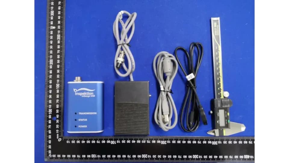





IO Isolation Board (Arduino/ATmega328) - How is it designed to be safe?
Inspektion engineering team · Published 7 September 2026 · Last updated 18 October 2026
Rewritten from the original article, first published May 2025
The IO isolation board separates the microcontroller circuit from field signals using optocouplers and solid-state relays. It requires checking coordinates and circuit design.
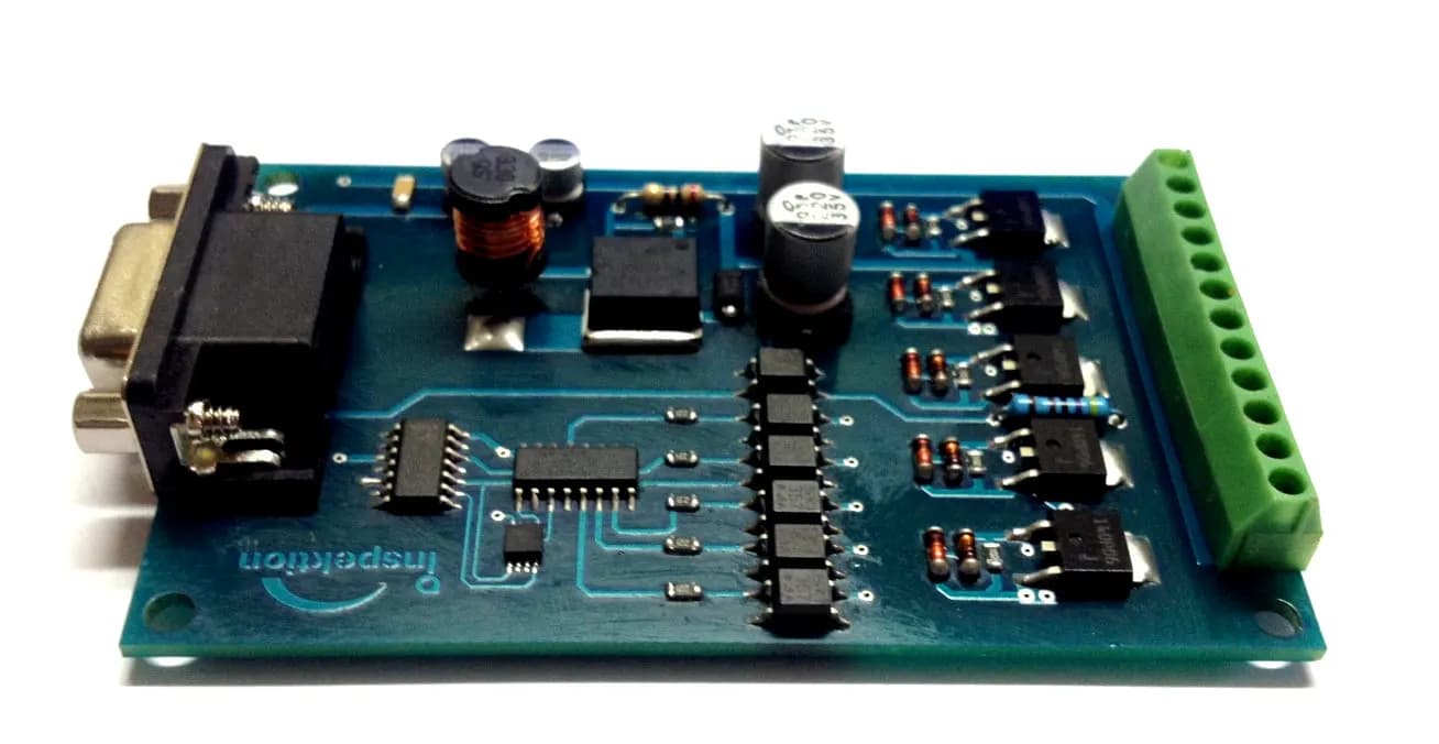
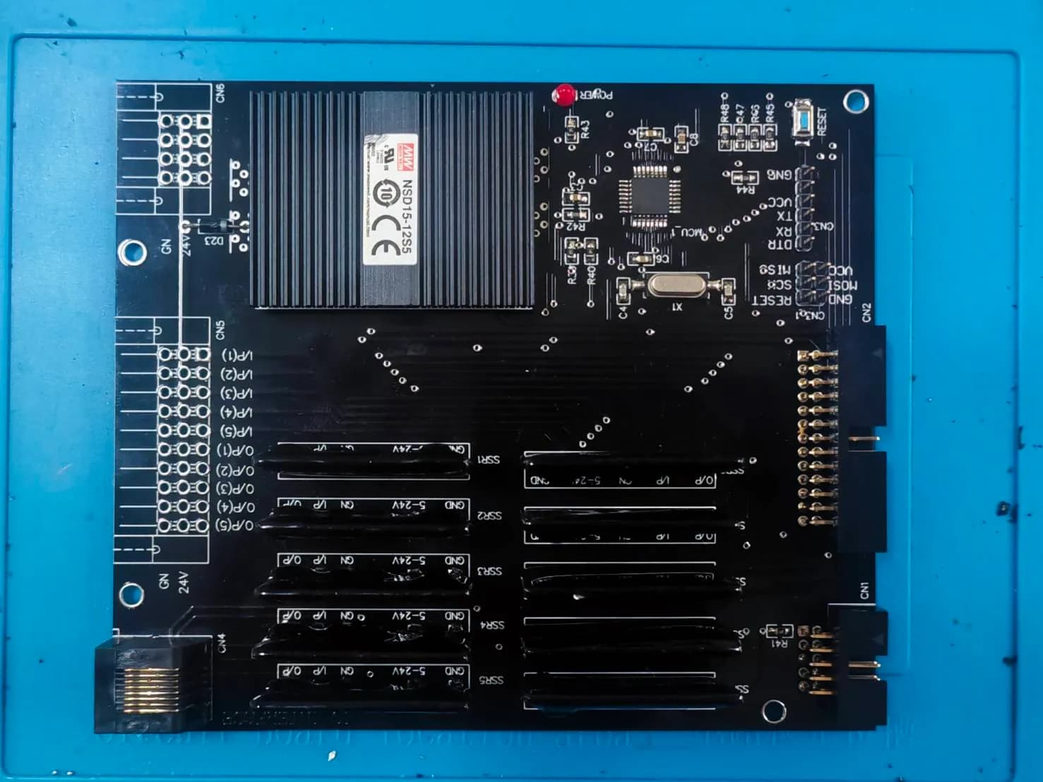 Image: Inspektion
Summary
- An I/O isolation board acts as an intermediary between a low-voltage (5V) microcontroller and high-voltage or high-current electrical loads.
- An optocoupler (PC817) electrically separates the ground of the control circuit from that of the power circuit. This helps isolate the signal circuit, but surge protection requires additional protective devices to be designed in.
- Using a solid-state relay (SSR) instead of a conventional mechanical relay allows fast, silent switching and a longer service life.
- A two-stage power supply design (LM2596 + LM7805) provides a stable 5V supply for the microcontroller.
What is an I/O isolation board?
What is an I/O isolation board?
An I/O isolation board is a circuit that acts as an intermediary between a low-voltage, damage-sensitive microcontroller (such as the ATmega328) and external loads with high voltage, high current or heavy electrical noise. It prevents damage on the load side from travelling back and destroying the control circuit.
Main components of the board
ATmega328 microcontroller
An 8-bit microcontroller with AVR RISC architecture, it has 23 I/O pins (8 pins are used to control the solid-state relays), 32KB of flash memory and 2KB of SRAM. It operates at 5V, which suits general Arduino work.
PC817 optocoupler
| Specifications | Value |
|---|---|
| Ground isolation voltage | 2.5 kVrms (5 kVrms on some models) |
| Voltage drop across the LED | Approximately 1.25V |
| Maximum collector-emitter voltage | 80V |
| Maximum collector current | 50mA |
| Switching speed | Approximately 18 microseconds |
| Package | 4-pin DIP |
A 220Ω current-limiting resistor limits the LED current to approximately 17mA from a 5V supply.
Solid-state relay (SSR)
- Controlled by 3–32V DC, with a low control current of approximately 5mA
- Choose an SSR that matches the load type, AC or DC, and the current rating of that model
- Available in zero-crossing, instant-on and DC switching types
- Advantages: silent operation, fast switching and a longer service life than mechanical relays, but a heat sink is required at high current
Two-stage power supply
An LM2596 (a buck converter) accepts an input of 4.5–40V and steps it down first, followed by an LM7805 (a linear voltage regulator) to provide a stable, low-noise 5V supply for digital circuits that are sensitive to voltage fluctuations. [1] [2]
Where can it be used?
- Factory automation — connecting sensor signals to high-power control equipment
- Home automation and motor control systems
- Air-conditioning systems (HVAC) and test and measurement instruments
Examples of our real work
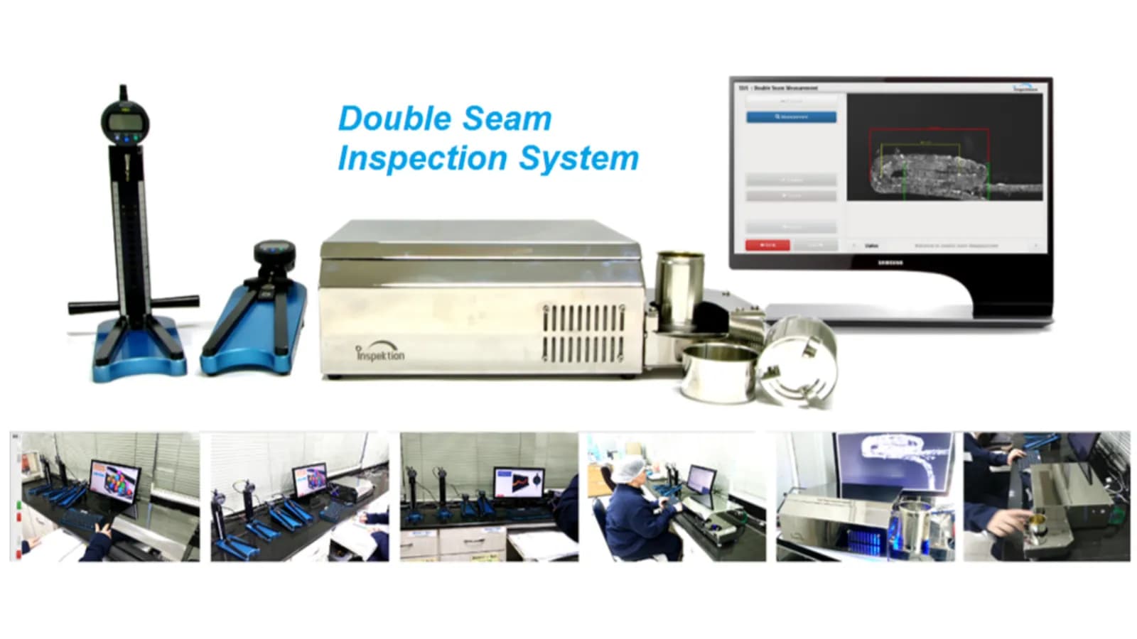
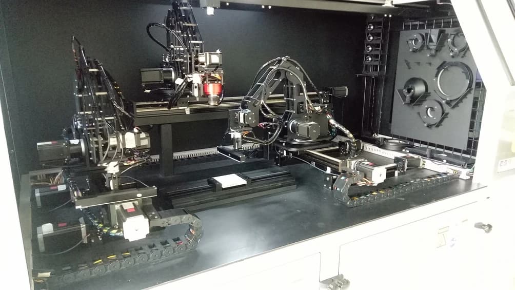
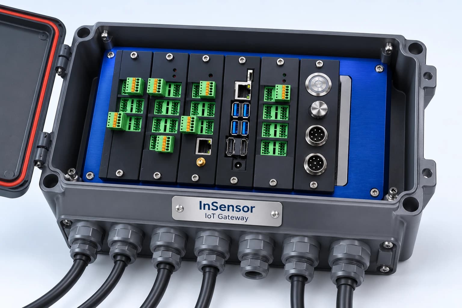
Connecting field equipment requires choosing a circuit that matches the signal and the load. Read about InSensor (X1 board) and see an example of hardware and embedded software work in the DSIS can seam inspection machine. These examples do not confirm the use of the same board or circuit as in this article.
Frequently Asked Questions
Is an optocoupler always necessary?
It should be used when the control circuit has to connect to loads with high voltage, high current or heavy electrical noise, to prevent damage from travelling back to the microcontroller.
How does an SSR differ from a conventional mechanical relay?
An SSR uses a semiconductor switch instead of mechanical contacts, so it operates silently and faster, with no wear from repeated switching. However, it needs good heat dissipation at high current.
Can a board like this expand its number of channels?
Basic boards are usually designed with a fixed layout based on the number of I/O pins on the microcontroller. To expand the channels, you need an I/O expander or a change to a microcontroller model with more pins.
References
- [1]
ATmega328P Datasheet — Microchip Technology
- [2]
LM2596 SIMPLE SWITCHER Power Converter Datasheet — Texas Instruments
- [3]
LM340/LM78xx Series Voltage Regulators Datasheet — Texas Instruments
- [4]
IO Interface Isolation Board — Open Source Code — GitHub (SupportINS)