




Design and manufacture of an RS232 isolation board driving 24-volt outputs for a gauge and workpiece measurement system manufacturer
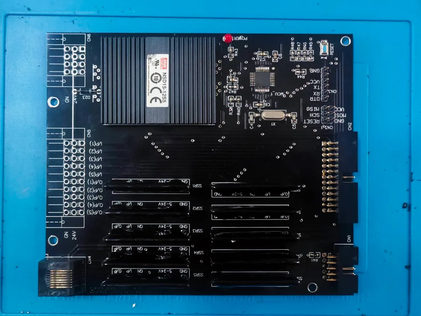
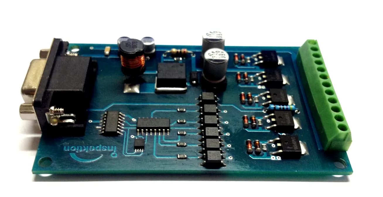
The IDB9 isolation board was designed and manufactured for a gauge and workpiece measurement system manufacturer. It lets a computer switch 5 channels of 24-volt outputs through an RS232 port. We designed the circuit in 2016, and the customer reordered the same board in multiple batches during 2018–2022.
- Industry
- General manufacturing
- Year
- 2016–2022
- Scope of work
- Circuit and PCB design, and manufacture of the Isolate Board IP DB9 (IDB9) in batches to purchase order. Specification according to the product documentation: 5 V supply, commands received via RS232 (DB9), 1 input channel, 5 digital output channels at 24–26 V each, current rating of no more than 3 A per channel (actual usable current depends on the power supply), wiring by screw terminal connectors (Terminal Block), board size 89 x 57.5 x 15 mm.
Summary
- The IDB9 signal isolation board is a board we designed in 2016 for a maker of gauges and workpiece measuring systems, so that a computer can switch 5 channels of 24 V output on and off through an RS232 port (DB9 connector).
- The command signal from the computer passes through an optocoupler before reaching the MOSFETs that drive the outputs. The 24–26 V comes from the DC-DC converter circuit on the board, which takes a 5 V supply.
- The product documentation states a current rating of no more than 3 A per channel, and states that actual usable current depends on the power supply.
- The customer reordered the same board model in several batches: a 2018 purchase order covers 10 sets, a 2020 project summary records delivery of all 22 sets, and the batch delivered in November 2022 was 10 sets (these are not combined into a single total).
The on-site brief
The customer needed a computer to switch 24 V devices on and off. The example in the product documentation is a status light that comes on when a measured workpiece fails. A computer's RS232 port cannot supply power at this level itself, so an intermediary board was needed to receive commands and drive the outputs instead.
What we did
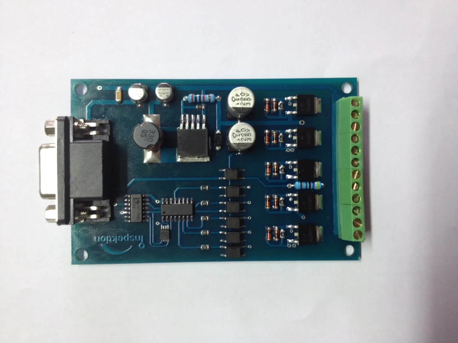
We designed the circuit and printed circuit board (PCB) of the Isolate Board IP DB9 (IDB9) in 2016. The computer sends commands through the DB9 connector, the signal passes through an optocoupler, and MOSFETs then switch 5 output channels on and off, using 24–26 V from the DC-DC converter circuit on the board. We then manufactured the boards in batches to purchase order.
- ComputerSends commands via RS232 (DB9)
- Optocoupler on the IDB9 boardCommand signal passes through before reaching the driver circuit
- MOSFETs drive 5 output channels24–26 V from the DC-DC circuit
- Status light / end deviceConnected via Terminal Block
Results
The customer reordered the same board model in several batches. A 2018 purchase order covers 10 sets, and a 2020 project summary records delivery of all 22 sets. The batch delivered in November 2022 was 10 sets, and receipts for all 10 sets were issued in December 2022.
How the brief came about
The challenge in this case was to let a computer control 24 V devices directly from a program. The customer is a maker of gauges and workpiece measuring systems. The usage example in the board's product documentation is controlling a status light when a measured workpiece fails.
Many measuring or inspection machines use a computer to decide the result, but that result has to appear as something operators can see immediately, such as a status light. These devices commonly run on 24 V, which a computer's RS232 port cannot supply itself, so an intermediary board is needed to receive commands and drive the outputs instead.
Requirements and constraints
The board's requirements come from the product documentation. The board receives commands via RS232 and uses a single 5 V supply, then generates 24–26 V on the board itself. The specification is as follows.
IDB9 board specification according to the product documentation
| Features | Value |
|---|---|
| Board power supply | 5 V |
| Command input | RS232 via DB9 connector |
| Input | 1 channel |
| Digital output | 5 channels, 24–26 V per channel |
| Current rating per channel | No more than 3 A (actual usable current depends on the power supply) |
| Output wiring | Screw terminal connector (Terminal Block) |
| Board size | 89 x 57.5 x 15 mm |
The limitation to be aware of is current. The 3 A figure is a per-channel rating according to the product documentation, while the current actually available when several channels are on at the same time depends on the power supply. Before using several channels at once, the total load must be checked against the power supply.
How the IDB9 board receives commands from a computer and drives 24 V
The IDB9 board receives commands from the computer through the RS232 port, passes the command signal through an optocoupler, and has MOSFETs switch each output channel on and off. The 24–26 V for the outputs comes from the DC-DC converter circuit on the board, so the computer only sends commands and does not have to power the devices itself.
- 1
The computer sends commands via RS232
The computer connects to the board with a cable into the DB9 connector, an RS232 serial port commonly found on industrial computers.
- 2
The command signal passes through an optocoupler
The command signal passes through an optocoupler (a chip that transfers a signal between circuits using light) before reaching the output driver circuit.
- 3
MOSFETs switch 5 output channels on and off
Each MOSFET (an electronic switch with no mechanical contacts) controls one output channel.
- 4
The DC-DC circuit generates 24–26 V on the board
The board uses a 5 V supply, and the DC-DC converter circuit on the board steps the voltage up to 24–26 V for the outputs.
- 5
Wiring devices at the screw terminals
Wires from status lights or end devices connect to the screw terminal connectors (Terminal Block) on the edge of the board, and can be removed and replaced without soldering.
An intermediary board like this gives a clear division of roles. The program on the computer only sends commands through a communication port, while powering the devices is handled by the driver circuit on the board. Boards of the same specification can also be ordered in batches, instead of wiring up circuits on site one machine at a time.
What is an optocoupler?
An optocoupler (also known as a photocoupler) is a chip with an LED and a light receiver in the same package. One side converts an electrical signal into light, and the other side receives the light and converts it back into an electrical signal. The signal therefore crosses from one circuit to another by light inside the chip. Whether the whole system has isolated grounds depends on the design of the surrounding circuits, including the power supply circuit.
Deliverables
What we deliver is the IDB9 board, in the quantity on the purchase order for each batch. The boards are manufactured from the circuit and printed circuit board (PCB) design we created in 2016.
We also prepared product documentation for the board. It states the specification in the table above and gives an example of use: controlling a status light.
How the customer reordered this board model
The customer reordered the same IDB9 board in batches, with purchase order or delivery documents from 2018, 2020 and 2022, and no redesign was needed. The sequence according to the documents is as follows.
- 2016: We designed the circuit and PCB of the IDB9 board
- 2018: Purchase order for 10 sets of the board
- 2020: Project summary records delivery of all 22 sets
- 2022: The customer ordered more; the batch delivered in November was 10 sets
The documents do not state whether the quantities in each period overlap, so we have not added the figures into a single total.
Results confirmed by purchase orders and deliveries
The confirmed result of this case is the repeat orders. This maker of gauges and workpiece measuring systems reordered the same IDB9 board model from 2018 to 2022.
We delivered 10 sets of the IDB9 board in November 2022 and issued receipts for all 10 sets in December 2022. This case has no information on how the boards performed on the customer's machines, so we report only the documented purchase orders and deliveries.
What we learned
This work offers 3 principles for designing boards that receive commands from a computer and drive devices in machinery.
- Having an optocoupler on the board does not mean the whole system has isolated grounds. If the job requires ground isolation or surge protection, it must be written as a requirement from the start, and both the signal path and the power supply circuit must be checked.
- The per-channel current rating and the power supply's capacity are two different values. Product documentation must separate them clearly, and the actual load must be checked when several channels are on at the same time.
- A board that customers reorder needs its circuit design, parts list and product documentation kept together as one set. In this work, the board model was designed in 2016 and the customer kept reordering it up to 2022.
How this approach can apply to your work
If your computer or program needs to control a status light or a 24 V device, you can use the same approach as this case: the computer sends commands and an intermediary board handles driving the outputs. What needs adapting depends on the control interface, the number of channels and the actual load of the end devices.
Reusable parts and parts that need adapting
| Part of the board | In this case | Needs adapting when |
|---|---|---|
| Command input | RS232 via DB9 connector | If your controller has no RS232 port or uses a different communication channel, the command input section must be redesigned |
| Number of output channels | 5 channels | If you need a different number of channels, the circuit design and board size must be adapted |
| Voltage and current | 24–26 V from the DC-DC circuit on the board | If the end device uses a different voltage, or draws high current when several channels are on at the same time, the power supply and driver circuit must be re-checked |
| Ground isolation | The command signal passes through an optocoupler before reaching the driver circuit | If your work requires ground isolation between the computer side and the device side, it must be set as a requirement and the power supply circuit designed to support it |
| Manufacturing | Manufactured in batches to purchase order from the existing design | If you need a large quantity of boards, or must fit them in a cabinet of limited size, the size and mounting positions must be agreed first |
- Summarise the number of output channels and the voltage and current the end devices actually use, including how many channels must be on at the same time.
- Specify the channel the computer or controller will use to issue commands, and the command format the program will send.
- State the board's power source, the size that will fit, and the mounting position in the cabinet or machine.
- Estimate the quantity per batch and the reorder plan, so the circuit design and parts list can be kept for the next batch.
Read more
- Case: PLC slide control system for a workpiece measuring machine
- InSensor: a sensor data collection device with an X1 Board inside
- AI / IoT consulting and system design service
- Custom system development service
- Article: another type of I/O signal isolation board (microcontroller + solid-state relay), not the IDB9 board
Images of the system and how it works
Technology used
Frequently Asked Questions
What can the IDB9 board do?
The IDB9 board receives commands from a computer through an RS232 port (DB9 connector) and switches 5 digital output channels on and off, at 24–26 V per channel. It is used to control status lights, such as a light showing that a measured workpiece has failed, or other end devices that use this power level. The product documentation states a current rating of no more than 3 A per channel, while the current actually available across several channels at once depends on the power supply. Please tell us the actual load so we can check it first.
Can this board isolate grounds or protect a computer against surges?
This board's documentation does not mention ground isolation or surge protection. What can be confirmed is that the command signal from the computer passes through an optocoupler before reaching the output driver circuit. If your work requires ground isolation between the computer side and the device side, or surge protection, please state it as a requirement from the design stage.
Can I reorder to the same specification?
Yes. In this case, the customer reordered the same board model in several batches, from a 2018 purchase order to a batch delivered in 2022.
Can this be done with a different number of channels, voltage or control port?
We need to look at the requirement first. We need to know the number of channels, the voltage and current of the end device, and the interface the controller uses to send commands. Only then can we say whether the existing design can be adapted or a new design is needed.
What are the price and production lead time?
There is no standard price. Price and lead time depend on the specification and the quantity per batch. Please request a quotation with your job details, and we will assess it against your actual requirement.