



Thermal image decoding and stitching module for electrical control cabinets, for the maintenance team of an industrial factory in Thailand
Customer: A large manufacturing group in Thailand
TIDM (Thermal Image Decoding Module) is a software module that reads temperature values from the image files of FLIR thermal imaging cameras, stitches images of an electrical control cabinet taken section by section into a single image, and reports the maximum and minimum temperature of each grid cell. We developed and delivered this module to the maintenance team of an industrial factory in Thailand in 2018–2019.
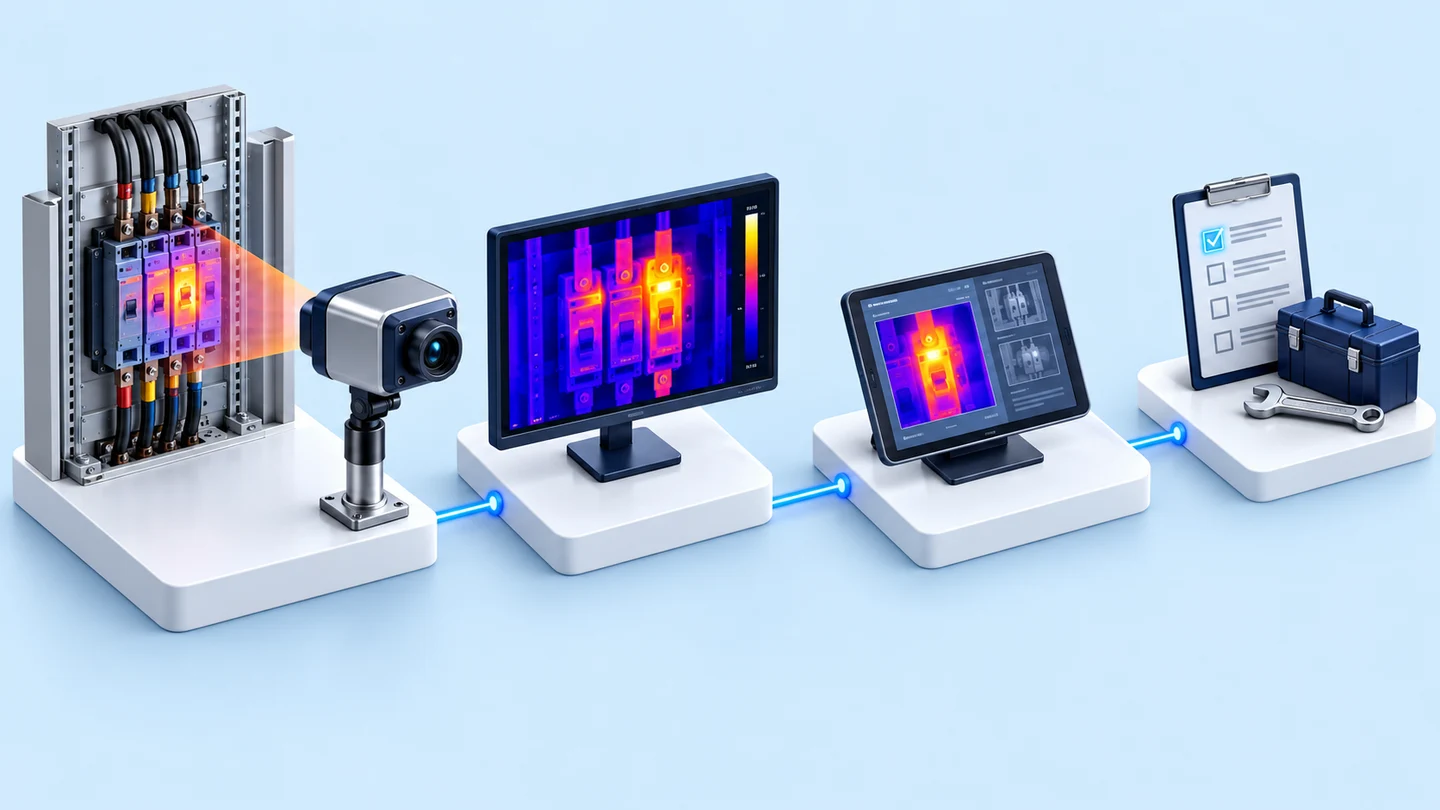
- FLIR thermal imaging cameraCapture the cabinet section by section, copy the .jpg files from the SD card
- Image decoding (TIDM)Colour + greyscale images on the same temperature scale
- Panorama stitchingOriginal image + thermal image
- Grid, reading maximum/minimum per grid cell
- Temperature results database
- Industry
- General manufacturing
- Year
- 2018–2019
- Scope of work
- 3 deliverables: the main program of the TIDM module with source code, for thermal image files from FLIR cameras; system design documents (system diagram, operating state diagram, database diagram, data flow diagram, algorithms and a list of the libraries used); and a study of approaches with further recommendations for files from Testo and InfReC cameras.
Summary
- TIDM is a software module that reads temperature values from the .jpg image files of FLIR cameras, stitches images of an electrical control cabinet taken section by section into a single image, and reports the maximum and minimum temperature of each grid cell.
- The module has 2 parts. The decoding part adjusts every image to the same temperature scale, and the panorama stitching part combines the section images into a single image of the whole cabinet.
- In 2018–2019 we delivered all 3 items of this work to the maintenance team of an industrial factory in Thailand: the program with source code, the system design documents, and a study of approaches with further recommendations for files from Testo and InfReC cameras.
- Panorama stitching depends on how the images are taken, so the image capture method was adjusted to a new sequence in this work.
- Reports for each inspection round, comparison of results between rounds, and alerts are not part of the delivered scope of work.
The on-site brief
The maintenance team inspects electrical control cabinets with thermal imaging cameras supplied by the customer (FLIR, Testo, InfReC), taking images section by section in rows and columns. The camera files store temperature data in a format specific to each manufacturer. The team wanted a program that reads temperature values from the files, stitches the images into a single image of the whole cabinet, and reports the maximum and minimum temperature of each section.
What we did
We developed the TIDM module in Python for .jpg image files from FLIR cameras. The module has 2 parts: a decoding part, which reads the raw data and adjusts every image to the same temperature scale, and a panorama stitching part, which combines the section images into a single image of the whole cabinet. The program then draws a grid on the image, reads the maximum and minimum values of each grid cell, and stores the results in a database.
Results
We delivered all 3 items according to the scope of work, with the image capture method adjusted to a new sequence. The module produces a single image of the whole cabinet and the maximum and minimum temperature of each grid cell, recorded in a database.
How the brief came about
The challenge in this case was to read temperature values from thermal image files of electrical control cabinets with a program, and to view the result for the whole cabinet in a single image. The customer's maintenance team inspects electrical control cabinets with thermal imaging cameras, taking images section by section in rows and columns, so the inspection result for one cabinet is several separate image files.
Wiring connections or devices in an electrical cabinet that are starting to develop a problem are often hotter than the area around them. A thermal imaging camera makes these spots visible without touching the equipment. The team therefore wanted an overview of the whole cabinet, with the maximum and minimum temperature of each section.
Requirements and constraints
The module had to work with the cameras and files the customer already had. This work did not include supplying cameras. The main requirements and constraints are as follows.
- The customer supplied its own thermal imaging cameras: FLIR, Testo and InfReC.
- The camera files store temperature data in a format specific to each manufacturer.
- The program takes .jpg image files from FLIR cameras, copied from the SD card to a computer.
- The output had to include both the original and the thermal image of the whole cabinet and the maximum and minimum temperature of each cell, saved to a database.
- Stitching depends on how the images are taken: they must be taken in rows and columns, the starting point of each image should not be far out of line, and the lighting in the area being captured should be evenly bright.
- Reports for each inspection round and comparison of results between rounds are not in the scope of work.
What is thermal image decoding?
Files from many thermal imaging camera models store more than the colour image shown on the screen. They also hold the raw data used to calculate the temperature of each point, in a format specific to the camera manufacturer. Decoding means reading this data out, so that a program can calculate, stitch images and store temperature values itself.
Why must thermal image files be decoded before stitching?
They must be decoded first because every image has to use the same temperature scale before being stitched into one. If each image uses its own scale, the same colour in two images may mean different temperatures. Adjusting the scale needs the temperature values from the raw data in the file, so this data has to be read out first.
We therefore divided the TIDM module into 2 parts. The first decodes the raw data and adjusts every image to the same temperature scale. The second stitches the images into a single image of the whole cabinet. Because every image uses the same temperature colour bar, the panorama of the whole cabinet can be read on one scale.
- 1
Capture the cabinet section by section in row and column order
The inspector takes thermal images of the electrical control cabinet section by section, in rows and columns. A clear capture sequence lets the program know which image joins to which.
- 2
Decode the thermal image files
The module reads the raw data that the FLIR camera stores in the .jpg file, converts it into a colour image and a greyscale image, then recalculates the temperature scale so that every image in the set uses the same temperature scale.
- 3
Stitch the images into a single panorama
The module stitches the section images into one large image, producing both the original image and the thermal image of the whole cabinet. The inspector can see locations hotter than their surroundings in a single image.
- 4
Draw a grid and read the temperature of each grid cell
The program draws a grid on the image, then reads the maximum and minimum temperature of each grid cell, with a temperature colour bar accompanying the image.
- 5
Store the results in a database
The resulting images and the temperature values of each image are saved to the database.
Deliverables
We delivered all 3 items according to the scope of work. The deliverables are as follows.
- The main program of the TIDM module with source code, written in Python, for .jpg image files from FLIR cameras
- System design documents: system diagram, operating state diagram, database diagram, data flow diagram, algorithms and a list of the libraries used
- A study of approaches with further recommendations for files from Testo and InfReC cameras
Results confirmed from the delivery
In 2018–2019 we delivered all 3 items of the TIDM module to the maintenance team of an industrial factory in Thailand, according to the scope of work. The delivered program produces 2 types of output. The first is a panorama of the whole cabinet, as both an original image and a thermal image using the same temperature colour bar. The second is the maximum and minimum temperature of each grid cell, saved to the database together with the images.
This case has no usage measurement figures, such as the number of cabinets inspected or time reduced, so we report only what was delivered and can be confirmed from the documents. The delivered program reads files from FLIR cameras. Testo and InfReC cameras are in scope as a study of approaches with further recommendations, and are not yet a delivered program.
What we learned
This work offers 3 principles for reading temperature values from thermal images.
- The image capture method is part of the system, not just a step before using the program. Panorama quality depends on the capture sequence agreed before capture begins.
- Temperature values must be on the same scale before they are compared. Camera images must have their raw data decoded and be adjusted to the same temperature scale before stitching or comparing colours between images.
- Support for each camera model must be confirmed from real files from that model, because file formats differ by manufacturer. The camera models a program is stated to support should therefore be based only on files that have been tested.
How this approach can apply to your factory
If your team already inspects electrical control cabinets with thermal imaging cameras, you can use the same approach as this case: decode the camera files, adjust every image to the same scale, stitch them into a single image, then read the value of each cell and store it in a database. The part that needs adapting is file reading, when your camera is a different brand or model.
Reusable parts and parts that need adapting
| System part | Reusable | Needs adapting when |
|---|---|---|
| File reading | Decoding .jpg files from FLIR cameras | The camera is another brand or stores files in a different format: real sample files must be checked first |
| Panorama stitching | Stitching images taken in rows and columns | The capture method has no fixed row and column order: the capture method must be defined first |
| Reading values per grid cell | A grid and the maximum and minimum values of each grid cell | Values other than maximum and minimum are needed: the calculation method must be agreed before development |
| Using the temperature results | Saving images and temperature values to a database | Reports for each inspection round or alerts are needed, which are outside the scope of this case: additional design is required |
Beyond the items in the table, 2 more matters should be agreed before development begins.
- Agree the test cases and a clear delivery date for sample files before development begins, so that testing can follow the plan.
- Decide in advance where the temperature results will be used next, such as reports for each inspection round or an alert system, so that the database structure can be designed to support it.
Start with one image set from a real cabinet
A set of thermal images of a real cabinet, with every section captured in order, is the data that allows both decoding and stitching to be tested most quickly.
Read more
- Custom inspection and control system development service
- AI / IoT consulting and system design service
- Annual system care and maintenance service
- InCBM — machine condition monitoring for maintenance planning
- Case study: analysis system for gas test results in transformer oil (DGA)
- Case study: prototype software for detecting slag in molten steel with a FLIR thermal camera
Technology used
Frequently Asked Questions
Which camera brands can this module read files from, and do I need to buy a new camera?
The delivered work supports .jpg image files from the FLIR cameras the customer already had, and did not include supplying cameras. Testo and InfReC cameras are in scope as a study of approaches with further recommendations, and are not yet a delivered program. If you use another camera model or brand, you need to send us real sample files to check first, and we can then assess how much further development is needed.
How should images be taken so they can be stitched into a panorama?
Take images section by section in row and column order, keep the starting point of each image from being far out of line, and keep the lighting in the area being captured evenly bright. In this case, the image capture method was also adjusted to a new sequence.
Do we also receive the source code and system design documents?
Yes. The delivered work in this case includes the Python source code of the TIDM module and system design documents: system diagram, operating state diagram, database diagram, data flow diagram, algorithms and a list of the libraries used.
Can this system produce reports or alerts when temperatures are abnormal?
The work delivered in this case does not yet include this. The module saves images and temperature values to a database. Reports for each inspection round, comparison of results between rounds, and alerts are outside the scope of work. If you need them, additional data structures and screens would have to be designed.
If I want a system like this, how much does it cost?
There is no standard price, because it depends on the camera model, the file format and what you want to do with the temperature results. Please contact us to request a quotation. We assess it from sample files and the actual scope of work.