




Mitutoyo digital gauge reader sending values to a computer over Wi-Fi and USB for quality measurement work (in-house research)
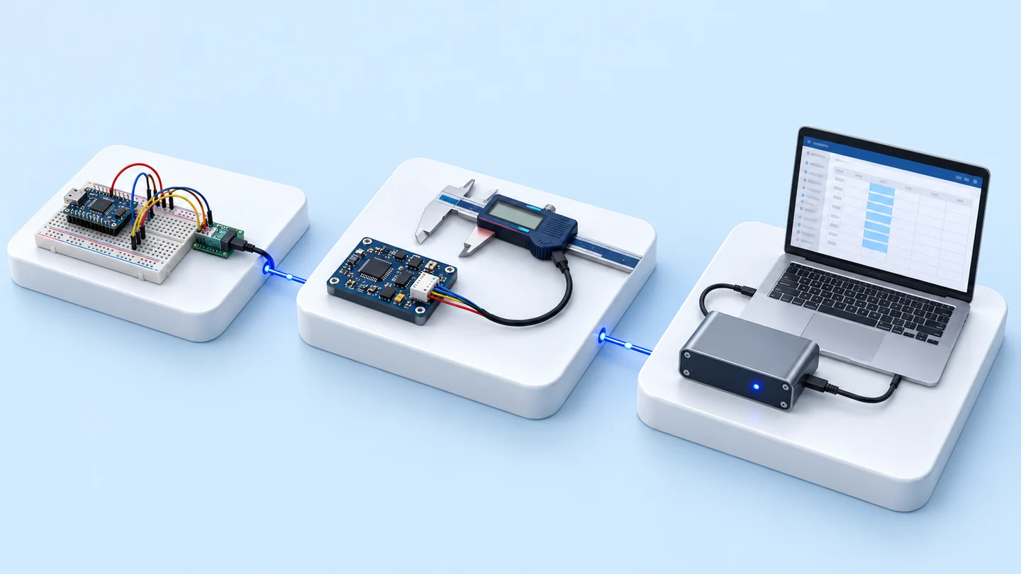
This reader takes values from a Mitutoyo digital gauge and sends them to a computer without anyone having to type them in. We built prototypes using 2 approaches in in-house research and development during 2015–2018: a Wi-Fi reader and a USB board that the computer sees as a keyboard. The timing of the work coincides with the 2017 InGauge USB 2.0 documents.
- Industry
- Services
- Year
- 2015–2018
- Scope of work
- Prototypes using 2 approaches: (1) a Wi-Fi reader on a NodeMCU board with a foot switch, a settings web page and the Gauge Reader program (Python) on the computer; (2) a USB board with an ATmega32U4 chip running Arduino-style v3 firmware with 3 modes: sending values when the computer requests them, sending values as soon as they are read (up to 4 channels in serial port mode), and USB HID keyboard mode · Our in-house research and development
Summary
- A prototype from our in-house research and development in 2015–2018 that takes values from the Digimatic port of a Mitutoyo digital gauge and sends them to a computer, instead of someone reading the figures on the gauge and typing each value by hand
- We built 2 approaches: a Wi-Fi reader on a NodeMCU board that sends values when the foot switch is pressed, and a USB board with an ATmega32U4 chip running v3 firmware
- The v3 firmware has 3 modes, supports up to 4 gauge channels in serial port mode, and has a keyboard mode (USB HID) that types values into a program, followed by Enter, with no additional software to install
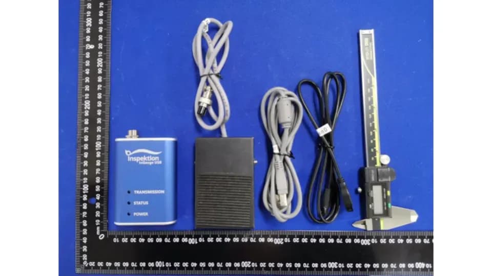
- The version the company currently sells and rents out is InGauge USB V2.1 from the 2020–2021 ITAP program, which redesigned the circuit and passed CE/FCC testing
The on-site brief
Measurement work still recorded by hand means reading the figures on the gauge display and typing each value into a program. This reader takes values from the Digimatic port (the data port on Mitutoyo gauges) and sends them directly to a computer.
What we did
We trialled 2 approaches. The first was a Wi-Fi reader on a NodeMCU board that sends values to the Gauge Reader program on a computer when the foot switch (a pedal switch that triggers sending) is pressed. The second was a USB board with an ATmega32U4 chip running v3 firmware, which has a keyboard mode (USB HID) that types the gauge value into a program, followed by Enter, when a button is pressed.
Test results with real workpieces
What we built and have evidence for is the v3 firmware with 3 modes, the keyboard mode version of the code, and the Wi-Fi reader with its manual. The documents do not record figures for the speed or accuracy of value transmission. Later, the 2020–2021 ITAP program redesigned the circuit, resulting in InGauge USB V2.1, which passed CE/FCC testing and is the version the company currently sells and rents out.
How the brief came about
This reader sends values from a digital gauge directly to a computer, instead of someone reading the figures on the gauge display and typing each value into a program. Digital gauges already display results as numbers, but if they still have to be retyped, recording results remains slow and typing errors can occur.
Many Mitutoyo digital gauge models, such as vernier calipers and micrometers, already have a Digimatic port for sending data. This prototype therefore starts by receiving values at that port. This work was our in-house research and development in 2015–2018.
Requirements and constraints
The prototype's documents do not record requirements as a separate list. The requirements below are summarised from what the prototype's code and manuals actually do.
- Read values from the gauge through the Digimatic port's signal pins: the clock pin (CLK), data pin (DAT) and request pin (REQ)
- Send values to the program open on the computer, followed by Enter, so that the next field is ready for input
- In the Wi-Fi version and keyboard mode, the person measuring triggers the send themselves by pressing the foot switch or a button
- Limitations: the modes that send values through the serial port need a program on the computer side to receive them, and keyboard mode takes values from one gauge at a time
How do sending values over Wi-Fi and over USB differ?
The Wi-Fi version requires the Gauge Reader program to be installed and open on the computer to receive values. The USB board in keyboard mode needs no additional software, because the computer sees the board as a keyboard. Both the Wi-Fi version and keyboard mode type values into the open program, followed by Enter, when the person measuring triggers the send.
Comparison of the 2 prototype approaches
| Title | Wi-Fi version | USB board version (v3 firmware) |
|---|---|---|
| Board used | NodeMCU | ATmega32U4 chip with firmware written Arduino-style |
| How sending is triggered | Pressing the foot switch | Button press in keyboard mode · Computer request, or sent as soon as a value is read, in serial port mode |
| Computer-side program | Requires the Gauge Reader program (Python) to be open | Keyboard mode needs no additional software installed |
| Settings | Wi-Fi name and password, and the destination computer's address, are set through the reader's web page | Plug USB cable into computer |
| Number of gauges | Not stated in the documents | Up to 4 channels in serial port mode · One at a time in keyboard mode |
How does the USB board work in keyboard mode?
- 1
Connect the gauge to the board
Run a cable from the gauge's Digimatic port to the ATmega32U4 chip board, then plug the board into a USB port on the computer.
- 2
The computer sees the board as a keyboard
The firmware in keyboard mode (USB HID) makes the computer recognise the board as a keyboard.
- 3
Press the button to send a value
When the person measuring presses the button, the board types the gauge value into the field where the cursor is, then presses Enter automatically.
- 4
Use with programs that accept typing
Values go into any program that accepts keyboard typing, such as a table in a spreadsheet program or a measurement recording form.
The v3 firmware has 2 further modes that send values through the serial port: sending when the computer requests it, and sending as soon as a value is read. These 2 modes both support up to 4 gauge channels but need a program on the computer side to receive the values.
How does the Wi-Fi reader on the NodeMCU board work?
- Connect the gauge and foot switch to the reader on the NodeMCU board
- Set the Wi-Fi name and password and the destination computer's address through the reader's settings web page
- Open the Gauge Reader program (written in Python) on the computer
- When the foot switch is pressed, the value is sent over Wi-Fi to the Gauge Reader program, which types it into the open program and then presses Enter automatically
What is USB HID?
HID (Human Interface Device) is the standard for devices such as keyboards and mice. A computer recognises this type of device straight away, so a device that acts as a keyboard can send figures to any program that accepts typing.
What we built and tested
We built the reader using 2 approaches, along with a computer-side program, firmware and manuals. The items are as follows.
- Manual for the Wi-Fi reader, which sets out the configuration steps through the reader's web page
- Gauge Reader program (Python), which receives values from the reader and types them into the open program
- USB board v3 firmware on the ATmega32U4 chip, with 3 modes
- A separate set of keyboard mode code, and the USB board circuit design
How does this prototype relate to InGauge?
This prototype falls in the same period as the 2017 InGauge USB 2.0 product documents, but it still has to be confirmed whether the v3 firmware is the same firmware as InGauge USB 2.0. The product the company currently sells and rents out is InGauge USB V2.1 from the ITAP program. The documented sequence of work is as follows.
- 2015–2018: In-house research and development, trialling the Wi-Fi reader and the USB board running v3 firmware
- 2017: InGauge USB 2.0 product documents
- 2020–2021: The ITAP program redesigned the circuit, resulting in InGauge USB V2.1, which passed CE/FCC testing
InGauge USB V2.1 has a serial port mode (Mode 1) and a USB HID keyboard mode (Mode 2), the same ways of sending values that the prototype's v3 firmware has.
Confirmed results from the prototype documents
What can be confirmed is the prototype's code and manuals. The v3 firmware on the ATmega32U4 chip has 3 modes and supports up to 4 gauge channels in serial port mode. The Wi-Fi reader's manual sets out the configuration steps and how to send values with the foot switch.
The prototype documents record the code and operating steps, but not figures for the speed or accuracy of value transmission, so this page does not report such figures.
For production line use, use InGauge
For sending values from measuring instruments to a computer on a production line, use InGauge USB V2.1, which has a redesigned circuit and passed CE/FCC testing. See the InGauge product page for details.
What we learned
This prototype offers 3 principles for sending values from measuring instruments to a computer.
- Send values through a channel the computer already recognises. The Wi-Fi version needs the Gauge Reader program kept open, while keyboard mode (USB HID) needs nothing extra installed. The less preparation the computer side needs, the easier it is to connect to existing software.
- Let the person measuring trigger the send when the value typed into the program must match the workpiece measured. The Wi-Fi reader and keyboard mode send values when the foot switch or a button is pressed, so the value entering the program is one the person measuring chose to send.
- Code that can send values still has to go through circuit design and standards testing as a further step before sale. The InGauge USB V2.1 currently on sale went through a circuit redesign and CE/FCC testing in the ITAP program.
How can you apply this approach to your measurement work?
If your gauge has a Digimatic port and you already record measurements in a program on a computer, you can use the same approach as this prototype: take values from the gauge's port and type them into the program as a keyboard would. For actual use, use InGauge rather than the prototype. What needs adapting depends on the receiving program and the number of gauges.
Reusable parts and parts that need adapting
| Part of the work | Reusable | Needs adapting when |
|---|---|---|
| Gauge value input | Reading values from the Digimatic port | Your gauge has no Digimatic port, or you do not yet have a cable matching the model. Check the gauge first. |
| Sending values to the program | Keyboard mode (USB HID), which types values followed by Enter | Your program takes values through the serial port. A computer-side program is needed to receive them. |
| Triggering the send | Push button or foot switch | Your working posture is different. Choose a switch position that still lets your hands hold the workpiece and gauge. |
| Number of gauges | One gauge at a time in keyboard mode | You need to read several gauges at once. This requires serial port mode and a program that supports it. |
- Check that the gauge you use has a Digimatic port and a cable matching the model
- Check whether your recording program can accept typed values or must receive them through the serial port
- Agree whether the person measuring will trigger the send with a button or a foot switch, and position it to suit the workstation
Read more
- InGauge — sends values from digital measuring instruments to a computer over USB
- Case: InGauge USB V2.1 circuit design in the ITAP program through to passing CE/FCC testing
- Case: InGauge USB rental and sale, sending measuring instrument values to a computer
- Case: Sending digital vernier caliper values to QC reports
- InQC — record measurements and view control charts on a tablet
- Custom system and device development service
Technology used
Frequently Asked Questions
If I want to use a device like this, which model should I choose?
Choose InGauge USB V2.1, the model currently available for sale and rental. It has a serial port mode (Mode 1) and a USB HID keyboard mode (Mode 2), the same as the prototype's v3 firmware, and it has passed CE/FCC testing.
How does this prototype relate to InGauge?
This prototype dates from the same period as the 2017 InGauge USB 2.0 product documentation, but it is still to be confirmed whether the firmware is the same. The 2020–2021 ITAP program then redesigned the circuit, resulting in InGauge USB V2.1, which has passed CE/FCC testing.
Do I need to install a program on the computer?
It depends on the approach. The USB board's keyboard mode (USB HID) needs no additional program, because the computer sees the board as a keyboard. The Wi-Fi version requires the Gauge Reader program to be open, and the serial port mode requires a program on the computer side to receive the values.
How many gauges can be connected at the same time?
The v3 firmware supports up to 4 gauge channels in serial port mode, while keyboard mode receives values from one gauge at a time.