




Redesigned the InGauge USB version 2.1 circuit to pass CE/FCC tests under NSTDA’s ITAP project
Organisation: National Science and Technology Development Agency (NSTDA) — ITAP project
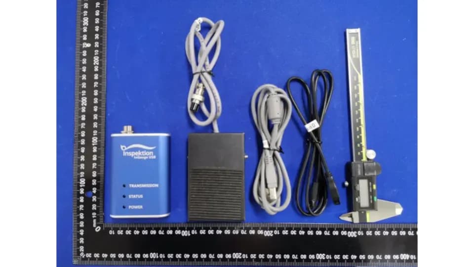
InGauge USB version 2.1 sends readings from digital measuring instruments to a computer. We redesigned its circuit under NSTDA’s ITAP project during B.E. 2563–2564. This version passed CE and FCC tests. According to the project summary report, assembly and testing time per unit decreased from 75–90 minutes to 15–25 minutes
- Industry
- Government
- Year
- 2020–2021
- Scope of work
- Analysing problems in the earlier circuit, designing a new circuit and PCB, building and testing a prototype, designing an aluminium enclosure, developing firmware, setting up incoming inspection and test procedures, and submitting for CE/FCC standards testing
- Duration
- 6 months (20 Jul 2020 – 20 Jan 2021)
Summary
- InGauge USB version 2.1 sends readings from digital measuring instruments to a computer as USB HID. We redesigned its circuit under NSTDA’s ITAP project over 6 months (20 July 2563 – 20 January 2564)
- We fixed the production method: a new PCB that arrives fully assembled from the manufacturer, with protection circuits against static electricity, reverse current and short circuits, along with new firmware written to a State Diagram
- Version 2.1 passed CE and FCC testing at the WALTEK Testing Group laboratory and works with Mitutoyo and Teclock measuring instruments
- According to the final report of the project, assembly and testing time was reduced from 75-90 minutes to 15-25 minutes, and the number of employees required was reduced from 2 to 1.
- Version 2.1 went on to become the InGauge product that we currently sell and rent out
The on-site brief
The first version of InGauge USB (V1.0) had to be soldered and wired on the circuit board unit by unit. Some units could not read values from digital vernier calipers, or misread the signal from the foot switch (a pedal switch that triggers sending a value). Assembly and testing took 2 staff 75–90 minutes per unit, about 75 percent passed testing, and the circuit had not been designed to support CE/FCC standards.
What we did
We worked with an electronic circuit expert serving as a consultant on the NSTDA ITAP program (Innovation and Technology Assistance Program) to design a new circuit and printed circuit board (PCB) that arrives fully assembled from the manufacturer, with protection circuits against static electricity, reverse current and short circuits. Our team developed the firmware, the aluminium enclosure and the pre-assembly incoming inspection procedure, then sent units to an external laboratory for CE and FCC testing.
Results
According to the project summary report, InGauge USB version 2.1 passed CE and FCC testing, works with digital measuring instruments from 2 brands, Mitutoyo and Teclock, and takes 1 staff member 15–25 minutes per unit to assemble and test. Units passing testing rose to more than 99 percent. The project closed as normal, and version 2.1 went on to become the InGauge product that we currently sell and rent out.
Measured results
- Total assembly and test time per unit, version 2.1 (maximum)
- 25minutes
- Total assembly and test time per unit, earlier version V1.0 (maximum)
- 90minutes
- Units passing testing, version 2.1 (more than)
- 99percent
- Staff needed for assembly and testing, version 2.1 (previously 2 people)
- 1
How the brief came about
The brief in this case was to make every InGauge USB unit delivered to customers work reliably and pass CE/FCC testing. InGauge USB is a device that takes values from digital measuring instruments, such as digital vernier calipers, and sends them to a computer or tablet over a USB cable as an HID (Human Interface Device — a device the computer sees as a keyboard). Measured values can therefore go straight into a field in a program without being written down on paper.
The first version (V1.0) had to be soldered and wired on the circuit board unit by unit. Some units could not read values from digital vernier calipers, or misread the signal from the foot switch. Units assembled incorrectly had to be scrapped, and the circuit had not been designed to support CE/FCC standards, which we aimed to pass before delivering the device to customers.
What is the ITAP program?
ITAP is a program of NSTDA (the National Science and Technology Development Agency) that helps the private sector develop technology by covering part of the costs, including fees for expert consultants. In this case, we applied for the project ourselves in order to develop our own product.
Requirements and constraints
The new version had to perform all the original functions of InGauge USB and fix the weaknesses of the first version within the project timeframe. The main requirements and constraints are as follows.
- Receive values from digital measuring instruments and send them to a computer via USB HID, as if typed on a keyboard
- Support a foot switch via an XLR connector so that staff can send values by stepping on it
- Design the circuit to support CE and FCC testing
- The prototype must be tested under high temperature and humidity before production
- Reduce work that requires skilled staff, because the first version had to be soldered and wired unit by unit
- Complete within the 6-month project period (20 Jul 2020 – 20 Jan 2021)
Why we redesigned the circuit instead of fixing existing units one by one
We redesigned the circuit because analysis of the earlier version found that the errors lay in the production method. Soldering and wiring each unit required skilled staff, and connecting many wires made mistakes easy. A printed circuit board (PCB) that arrives fully assembled from the manufacturer therefore removes manual soldering and wiring from our process.
We did not change what the device does; we changed the circuit, the production method and the test method. Protection circuits against static electricity, reverse current and short circuits were included from the design stage so that the circuit would support CE/FCC testing. Our team wrote new control firmware following a State Diagram (a diagram of operating states).
Responsibilities on this work were clearly divided. The project's consulting expert handled circuit analysis and design, while our team handled the firmware, the enclosure and the production steps.
Deliverables
When the project closed, we had InGauge USB version 2.1 along with production and testing procedures for producing this version. The main items are as follows.
- New circuit and PCB that arrive fully assembled from the manufacturer, with protection circuits against static electricity, reverse current and short circuits
- Aluminium enclosure that we designed and had manufactured by a contractor
- Control firmware based on a State Diagram, already tested at a real site
- Pre-assembly incoming inspection procedure for the circuit, with test results recorded as digital files
- Cable labels, and a manual with example clips for each step
- CE and FCC test results from an external laboratory
How InGauge USB version 2.1 developed from a project into a product
We developed version 2.1 in sequence, from finding the cause, designing the circuit and testing the prototype to setting up production steps and sending it for CE/FCC testing. After the project closed, this tested version went on to become the InGauge product that we sell and rent out.
- 1
Find the cause of the problems in the earlier version
Looked for the cause in the earlier version's production method.
- 2
Redesign the circuit and PCB
Redesigned the circuit and PCB based on the causes found.
- 3
Test the prototype and make the aluminium enclosure
Tested the prototype under high temperature and humidity, then made the enclosure.
- 4
Develop firmware and set up incoming inspection
Wrote the firmware, tested it at a real site and set up the incoming inspection procedure.
- 5
Send for CE and FCC testing
Sent units to an external laboratory for CE/FCC testing.
For real-world use after the project, see the case on renting and selling InGauge USB to factory QC departments, which uses InGauge USB version 2.1
Results confirmed by the project summary report
According to the project summary report, InGauge USB version 2.1 passed CE and FCC testing and takes 15–25 minutes per unit to assemble and test, compared with 75–90 minutes for V1.0. The work takes 1 staff member instead of 2, and units passing testing rose from about 75 percent to more than 99 percent.
The 15–25 minutes covers only assembly and testing at our company, because the circuit boards arrive fully assembled from the manufacturer. The figures in this section are values that we recorded and reported to the project ourselves.
WALTEK Testing Group in Shenzhen tested version 2.1 to CE (EN 55032 / EN 55035) and FCC Part 15 Subpart B standards. The report also confirms that this version works with digital measuring instruments from 2 brands, Mitutoyo and Teclock.
Comparison of the earlier InGauge USB version and version 2.1, according to the project summary report
| Title | Earlier version (V1.0) | Version 2.1 |
|---|---|---|
| Total assembly and test time per unit | 75–90 minutes | 15–25 minutes |
| Staff required | 2 people | 1 person |
| Units passing testing | About 75 percent | More than 99 percent |
| CE/FCC standards | Not yet designed to support them | Passed testing |
CE/FCC covers InGauge only
The CE and FCC test results in this case apply only to the InGauge USB hardware. They do not cover our software or other products, and they are not a certification of the company.
What we learned
This work offers principles for developing electronic devices that have to be produced repeatedly across many units.
- Fix the production method before adding inspection. If errors come from manual soldering and wiring, designing the circuit board to arrive fully assembled from the manufacturer removes that point of failure from the process.
- The standards to be passed are design requirements, not a final step. The first version was not designed to support CE/FCC, so in version 2.1 the protection circuits against static electricity, reverse current and short circuits were in the design from the start.
- Production steps must be transferable. Incoming inspection with results recorded as digital files, cable labels and example clips in the manual mean that quality does not depend on only a few skilled people.
How this approach can apply to your work
If you are developing an electronic device for repeated production, you can follow the same work sequence as this case: find the cause in the production method, design the circuit to support the standards it must pass, then set up an incoming inspection procedure that can record results. What you need to adapt is the standards and the operating conditions of your own device.
Reusable parts and parts that need adapting
| Part of the work | Reusable | Needs adapting when |
|---|---|---|
| Finding the cause | Collecting design, assembly and test data on the earlier version before redesigning | No earlier version to compare with: test data must be collected from the first prototype onwards |
| Circuit design | PCB that arrives fully assembled from the manufacturer, and protection circuits against static electricity, reverse current and short circuits | Where the device uses different power or signals from InGauge, protection circuits must be designed for the actual operating conditions |
| Standards to be passed | The work sequence: design, test the prototype, then send to a test laboratory | Where the target market requires standards other than CE/FCC, the standards must be defined before design begins |
| Incoming inspection and production | Pre-assembly incoming inspection of circuits, results recorded as digital files, cable labels and clips in the manual | Where the assembly steps differ from this case, timing must be measured and inspection points defined anew |
| Use with measuring instruments | Sending values via USB HID and stepping on a foot switch to send values | Where the measuring instrument is a brand or model other than Mitutoyo and Teclock, it must first be tried in real use |
If you plan to use InGauge on your production line
If you plan to buy or rent InGauge rather than develop your own device, check these points before deciding
- The brand and model of the measuring instruments you use. The project report covers testing with Mitutoyo and Teclock; other sub-models should be tried in real use first
- The destination program that will receive the values, such as Excel, an existing QC system or the InQC app on a tablet, because InGauge sends values as if typed on a keyboard
- The nature of your measuring work, whether a foot switch is needed, and the number of measuring points that need a device connected
- Outright purchase or rental. InGauge is available both to buy outright and to rent monthly. See prices on the product page
Try connecting it to your measuring instruments first
If you are not yet sure whether your existing measuring instruments can connect, send us the brand and model for us to check, or start by renting to try it on a real line before buying.
Read more
- InGauge — sends values from digital measuring instruments to a computer over USB
- InQC — SPC app on tablet, receiving values from InGauge
- Case: InGauge USB rental and sales
- Case: digital gauge reader over Wi-Fi and USB from in-house research
- Case: Sending digital vernier caliper values to automatic QC reports
- AI / IoT consulting and system design service
- What is SPC and P-Chart? How does a factory manager read control charts?
Technology used
Frequently Asked Questions
How does InGauge USB version 2.1 differ from the earlier version?
Version 2.1 uses a newly designed circuit and PCB, supplied fully assembled by the manufacturer. It has protection circuits against electrostatic discharge, reverse current and short circuits, is housed in an aluminium enclosure, and passed CE and FCC tests according to the project summary report. Assembly and testing time per unit fell from 75–90 minutes to 15–25 minutes.
Which brands of measuring instrument can InGauge be used with?
The project summary report states that it works with digital measuring instruments from 2 brands, Mitutoyo and Teclock. Each brand has many sub-models, so please tell us which model you use so that we can check it first.
What do the CE/FCC test results cover?
They cover the InGauge USB hardware under the CE (EN 55032 / EN 55035) and FCC Part 15 Subpart B standards, tested by WALTEK Testing Group. They do not cover our other products and are not a certification of the company.
What role did NSTDA play in this project?
NSTDA approved the project under the ITAP program and supported part of the costs, including consulting fees for the electronic circuit specialist who worked with us. We submitted the project and own the product, while the firmware, enclosure and production process were our team's work.
If I am interested in using InGauge, how do I get started?
See the details and prices for outright purchase or monthly rental on the InGauge product page, then tell us the brand and model of your measuring instrument and the program that will receive the values, so that we can help check them before you buy or rent.