




Controller and teaching software for a 4-axis SCARA robot arm prototype for factory pick-and-place work, a government-funded project in Thailand
Organisation: Thai-German Institute (TGI)
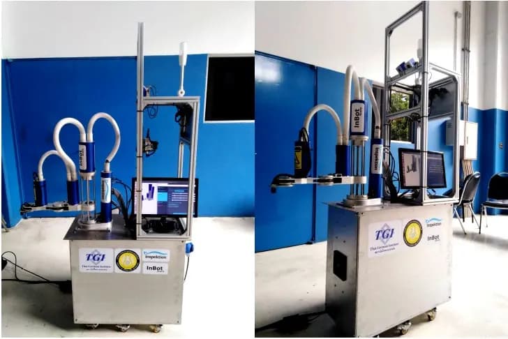
We developed the controller and software for a 4-axis SCARA robot arm prototype that lets users teach pick-and-place poses joint by joint on screen and trial-run them in a 3D model before commanding the real arm. This work was part of a 2018 technology product development project with government funding. We delivered 1 prototype set, and the prototype underwent the project's evaluation on 15 March 2019.
- Industry
- Government
- Year
- 2018–2019
- Scope of work
- Design, build and test 1 set of a 4-axis SCARA robot arm prototype (handling workpieces up to 1 kilogram, with a working radius of at least 400 millimetres), along with an NVIDIA TX1 control cabinet, teaching software and a 3D simulation model. Prepare progress reports, a final report and an operation and maintenance manual, and pass on how to use it to the private company taking part in the project.
- Duration
- 8 months under the contract (30 March – 30 November 2018)
Summary
- We developed the controller and software for 1 set of a 4-axis SCARA robot arm prototype in a 2018 technology product development project with government funding.
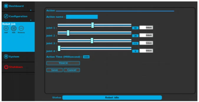
- Users teach poses on the Robot Job screen by moving the joints one axis at a time, setting the pose time and pressing TEACH, then trial-run them in a 3D model before commanding the real arm.
- The evaluation form dated 15 March 2019 records that the machine was fully assembled, could be tested against the specified functions and had a safety protection system, along with a recommendation to fix the grounding and electrical signals and then retest.
- What we built and could demonstrate are the pose teaching screen and the 3D model. The AI mode for learning to grasp, ROS support and history storage on a Cloud Server are targets under the project's requirements.
- We tested the prototype robot arm program with a steel stamping press at the factory of the private company taking part in the project. The next step after the prototype is to test picking real workpieces from a machine on a production line.
The on-site brief
Imported robot arms need specialists to set up their programs, and their controllers are often tied to a single motor brand, so machine prices and repair costs are beyond the means of small and medium-sized factories (SMEs). The project needed a domestically developed robot arm controller that technicians, electricians or staff with basic computer skills could configure and operate themselves.
What we did
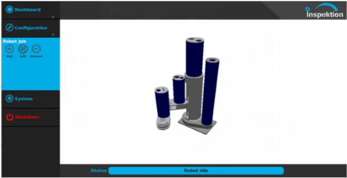
We designed and built 1 set of a 4-axis SCARA robot arm prototype (an arm that moves in the horizontal plane, suited to pick-and-place work), with a control cabinet using an NVIDIA TX1 processing board and control software. Users create a job sequence on the Robot Job screen, move the joints one axis at a time, then press TEACH to save the pose. They then trial-run the pose sequence in a 3D model (Simulation) before commanding the real arm.
- Robot Job screenTeach poses joint by joint, then press TEACH
- 3D modelTrial run in simulation
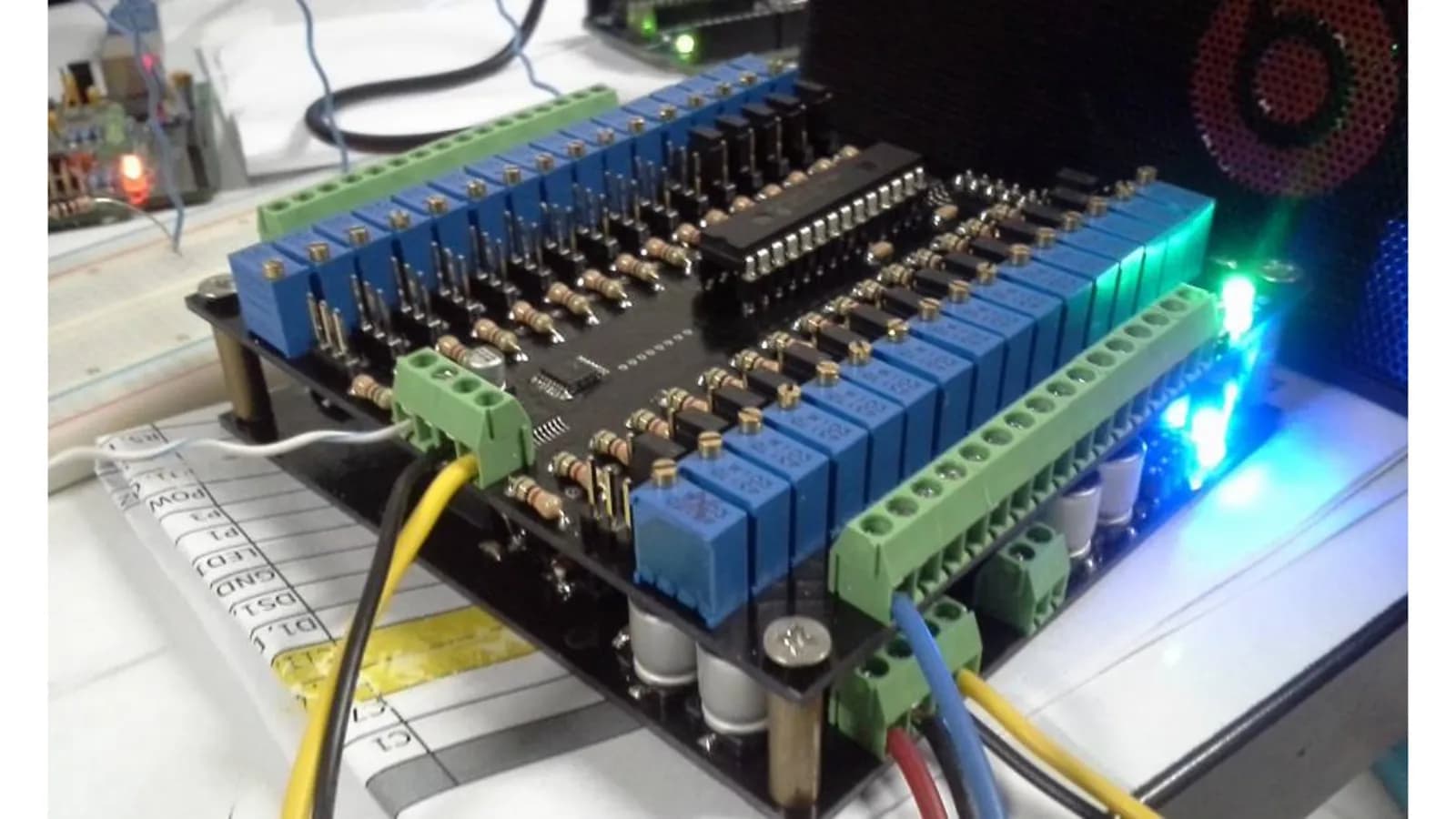
- NVIDIA TX1 control cabinetConfigured over LAN as per the requirements
- 4-axis SCARA robot armReceives commands via UART at the motor driver
Results
We closed the project under the contract, delivering 1 prototype set with a final report and an operation and maintenance manual. The evaluation form dated 15 March 2019 records that the machine was fully assembled, could be tested against the specified functions and had a safety protection system, along with a recommendation to fix the grounding and electrical signal issues and then bring it back for retesting. The next step after the prototype is to test picking real workpieces from a machine on a production line.
How the brief came about
The brief for this case was a domestically developed robot arm controller that factory staff could configure themselves without writing programs. Imported robot arms need specialists to set up their programs, and their controllers are often tied to a single motor brand, so machine prices and repair costs are beyond the means of small and medium-sized factories (SMEs).
This work was part of a 2018 technology product development project funded by the Bureau of Technology Promotion and Transfer, Office of the Permanent Secretary, Ministry of Science and Technology, and carried out with a government institute. A private company co-invested as the prototype user. The contract period was 8 months, from 30 March to 30 November 2018.
Requirements and constraints
The prototype had to be a small pick-and-place robot arm that general users could configure, and it had to be safe for people around the machine. The main requirements and constraints are as follows.
- 1 set of a 4-axis SCARA robot arm, handling workpieces up to 1 kilogram, with a working radius of at least 400 millimetres
- Technicians, electricians or staff with basic computer skills must be able to configure and operate it through the screen
- The robot arm rotates quickly and forcefully, so it must have an Emergency Stop button, a barrier around the area and warning signs around the working radius
- The power supply must deliver enough current, otherwise the robot arm cannot work at full capacity
- The project requirements also include an AI mode that learns to grasp workpieces of similar size, shape and weight, ROS support (Robot Operating System, a common software suite for robot development), configuration and operation from a computer on the LAN, and storage of status history on a Cloud Server
Why let users teach poses on screen and trial them in a 3D model before running the real machine?
We chose on-screen pose teaching because the project's target users are technicians and staff who do not write robot programs. We chose to trial in a 3D model first because the robot arm rotates quickly and forcefully, so users should find incorrect poses in the simulation before the real arm moves.
The control cabinet uses an NVIDIA TX1 processing board, which commands the motor driver via UART (a serial data communication channel between the control board and the motor driver). The steps for use according to the manual are as follows.
- 1
Install the controller on the robot arm
Connect the control cabinet to the robot arm's motor driver according to the operation manual
- 2
Load the robot arm's 3D model
Open the program and upload the robot arm's drawing to the system. The screen shows the 3D model used as the simulation.
- 3
Create the robot job and teach poses
In the Robot Job menu, users can add, edit or delete jobs. For each pose, they enter a name, move the joint position sliders one axis at a time, set the pose time in milliseconds, then press TEACH to save it.
- 4
Trial run in the simulation
Command the 3D model to move through the taught pose sequence to check that the poses are correct before letting the real robot arm move
- 5
Command the real robot arm
Once the pose sequence is correct in the simulation, the user commands the robot arm to work through the same sequence
What are a SCARA robot arm and pose teaching (Teach)?
A SCARA robot arm is a robot arm whose main joints rotate in the horizontal plane, with a vertical axis at the end of the arm, suited to picking and placing workpieces on a table or conveyor. Pose teaching means taking the robot arm to the required positions and saving them as steps so that the arm repeats them in sequence, instead of programming it with commands.
Deliverables
We delivered 1 set of a 4-axis SCARA robot arm prototype with a control cabinet, software and project documents. The delivered items are as follows.
- Robot arm prototype with a control cabinet using an NVIDIA TX1 processing board
- Control software with Dashboard, Configuration and Robot Job menus, plus a pose teaching screen and 3D model
- Progress reports and final report
- Operation and maintenance manual
- Transfer of operating know-how to the private company participating in the project
Prototype evaluation and test results
The project's evaluation form dated 15 March 2019 records that the prototype was fully assembled, could be tested against the specified functions and had a safety protection system. The same form recommended fixing the grounding and electrical signal issues and then bringing it back for retesting.
During the project, we tested the robot arm program with a steel stamping press at the factory of the private company taking part in the project, and demonstrated its operation to the team from the institute co-running the project. We closed the project under the contract. The next step after the prototype is to test picking real workpieces from a machine on a production line.
Parts that remain targets under the requirements
The AI mode for learning to grasp, ROS support and history storage on a Cloud Server are in the project requirements. What we built and could demonstrate are the pose teaching screen and the 3D model. The 3 parts above must be tested for results before being put to use.
What we learned
This work offers 3 principles for developing robot arm prototypes and controllers
- The test method for every function must be written down from the requirements stage. The acceptance criteria for this work covered electrical power, working radius and the emergency stop button, but not the AI mode, ROS or the Cloud Server. When every function has a test method from the start, all parties can agree on what is a target and what is a tested result.
- A prototype's electrical system must be checked at the real site from the early stages. The recommendation on grounding and electrical signals on the evaluation day shows that a demonstration alone is not enough; it must be tested with the machines the robot arm will work with.
- A robot arm that rotates quickly and forcefully should go through simulation before every real movement, and it must have an emergency stop button and a barrier around the area from the first day of testing.
How this approach can apply to your factory
If your factory has repetitive pick-and-place work with lightweight workpieces and you want technicians to adjust poses themselves, you can use the same approach as this case: teach poses on screen and trial them in simulation before running the real machine. What needs adapting is the work size, the type of robot arm and the connection to your machines.
Reusable parts and parts that need adapting
| System part | Reusable | Needs adapting when |
|---|---|---|
| Pose teaching | Robot Job screen where joints are moved one axis at a time before pressing TEACH | If your robot arm has a different number of axes or is a different type from the 4-axis SCARA, the joint settings screen must be adapted |
| Simulation | 3D model built from the robot arm's drawing | Requires the drawing of the actual robot arm your factory uses |
| Controller | An approach that separates the processing board from the motor driver, communicating via UART | If your motor driver uses another communication channel, first check how it takes commands |
| Work size | Workpieces up to 1 kilogram, radius of at least 400 millimetres | Heavier workpieces or a wider radius require the mechanism and motors to be reassessed |
| Working with machines | The program has been tested with a steel stamping press, but there is still a recommendation to fix the grounding and electrical signals, and real workpieces have not yet been picked | Grounding, signals and real workpiece picking must be tested with your machines before use on a production line |
- Have the size, shape and weight of the workpieces ready, as well as the distance the robot arm must reach
- Identify the machines the robot arm must work with and the signals to be exchanged between them
- Plan the barrier around the working radius, the emergency stop button positions and a power supply that can deliver enough current
- Prepare spare motors and electrical system inspection rounds according to the manual to reduce machine downtime
Images of the system and how it works
Technology used
Frequently Asked Questions
Can this robot arm really learn grasping poses by itself?
What can be confirmed is teaching poses through the screen: the user moves the joints one axis at a time, then presses TEACH to record them as a job sequence. The AI mode, which learns to pick up and grip workpieces of similar size, shape and weight, is a target under the project's specification, and its results must be tested before use.
What safety preparations are needed around the robot arm?
The robot arm rotates quickly and with force, so it needs an Emergency Stop button, the area must be cordoned off, and warning signs must be placed around its working radius. The power supply must deliver enough current, and the pose sequence should be trial-run in the 3D model before the real robot arm moves.
How much weight can the robot arm carry, and how far can it reach?
The prototype is a 4-axis SCARA robot arm that handles workpieces weighing no more than 1 kilogram and works within a radius of at least 400 millimetres. If your workpieces are heavier than this or need a longer reach, the mechanism and motors must be reassessed.
Who funded this project, and what kind of work is it?
This work falls under the 2018 Technology Product Development Project, funded by the Bureau of Technology Promotion and Transfer, Office of the Permanent Secretary, Ministry of Science and Technology, and carried out with a public-sector institute. It is prototype development work under contract, with a duration of 8 months, and an evaluation of the results took place on 15 March 2019.
If we want a robot arm controller for factory work, what information should we prepare?
Prepare the size, shape and weight of the workpieces, the distance the robot arm must reach, and the machines it must work with. We will survey the site first, then propose an approach and a quotation.