




Camera-based parts counting system on a vibratory feeder (Machine Vision Counter) for an industrial machinery customer
Machine Vision Counter is a camera-based parts counting system that we developed and installed on a vibratory feeder for an industrial machinery customer in 2016–2017. It counts 5 types of parts by feeder lane and signals the machine to stop the feeder when the count nears and when it reaches the quantity set by the user.
- Industry
- General manufacturing
- Year
- 2016–2017
- Scope of work
- Development of the Vision Counting part counting program; supply of a Global Shutter camera, lens, 5 lighting sets, processing unit, display and router; installation and adjustment of the camera position on the customer's machine; connection of the 24V power system and of 1 Input channel and 2 Output channels to the machine; together with a user manual and an 8-item work checklist
- Duration
- 2016–2017
Summary
- Machine Vision Counter is a camera-based part counting system that we installed on a vibrating-track part feeder for a customer in the industrial machinery sector during 2016–2017
- The Vision Counting program divides the image into lanes following the track and counts 5 part types as they cross the counting line (Line Counter). Users can add new part models themselves by training a model from sample images
- The system sends signals on 2 Output channels for the machine to stop the feed track when the count is nearly complete and when it is complete, and receives a signal on 1 Input channel from the Reset button on the machine
- The detection model only finds parts in the image. Counting and signalling follow the counting line and the quantity set by the user
- We closed out the job in May 2017, together with a user manual and an 8-item work checklist
The on-site brief
The customer wanted a vibrating-track part feeder (Vibratory Feeder) to count parts to exactly the quantity set. The test criterion was counting with “no shortfall and no excess”. There are 5 part types running together across multiple lanes, so the system had to be able to switch part models at the machine and signal the machine to stop feeding once the count was complete.
What we did
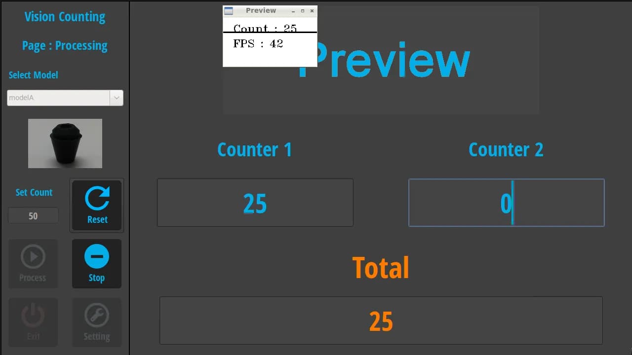
We developed a Vision Counting program on a processing unit connected to a Global Shutter camera mounted above the vibrating track and 5 lighting sets. The program divides the image into lanes following the track, counts each part as it crosses the counting line (Line Counter), and lets users add part models themselves by training a detection model from sample images, with at least 200 images per part model according to the manual. When the count reaches the set quantity, the system sends an Output signal for the machine to stop the feed track, and the Tower Light turns green for about 4 seconds.
- Global Shutter camera + lightingViews parts on the vibrating track, separated by lane
- Processing unitWorkpiece detection model trained on sample images
- Vision Counting programCounting line + per-channel counters + total
- Input/Output signals with the machineStops the feed track + Tower Light
Results
We installed and tested the system on the actual machine, delivered the equipment set to the customer in January 2017 and closed out the final phase in May 2017, together with a user manual and an 8-item work checklist. Users at the machine can select the part model and set the count quantity themselves.
How the brief came about
The challenge in this case was to count parts on a vibrating-track part feeder to exactly the quantity set, then have the machine stop feeding once that quantity was reached. The customer is in the industrial machinery sector. There are 5 part types on the track, running together across multiple lanes.
The program's test criterion required counting with “no shortfall and no excess” for every part type. If the count falls short or goes over, the work of dividing parts by quantity has to be recounted or corrected afterwards.
What is a vibrating track (Vibratory Feeder)?
A vibrating track is a part feeder that uses vibration to move parts along a track and arrange them into rows or lanes before passing them to the next process. In this case, the camera views the parts travelling on the track to count them.
Requirements and constraints
The system had to work on the customer's machine and be usable at the machine without changing the program. The main requirements and constraints were as follows.
- Count 5 part types: flat round parts in several sizes, parts with a central hole, and plug-shaped parts
- Parts run together across multiple lanes, so counting must be separated by track lane
- Users at the machine must be able to select the part model, set the count quantity (Set Count) and add new models themselves
- The system must connect to the machine through 1 Input channel and 2 Output channels
- The equipment set must use a 24V power system connected to the machine's main power system
How does the system count multiple part models across multiple lanes with a camera?
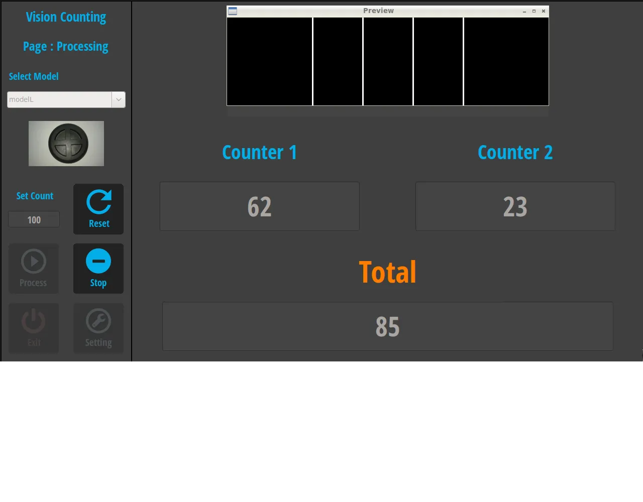
The system counts multiple part models across multiple lanes by splitting the work into 2 tasks. The detection model for each part model finds the parts in the image, while counting uses a counting line (Line Counter) on an image divided into lanes following the track. When a part crosses the line, the program adds one to the count.
We chose this approach because there are many part types and part models must be switched at the machine. Giving each part model its own detection model lets users add new part models from the screen, while counting and signalling still follow the counting line and the quantity set by the user. Users can therefore check which rules the system counts by.
- 1
Add part models and train the model
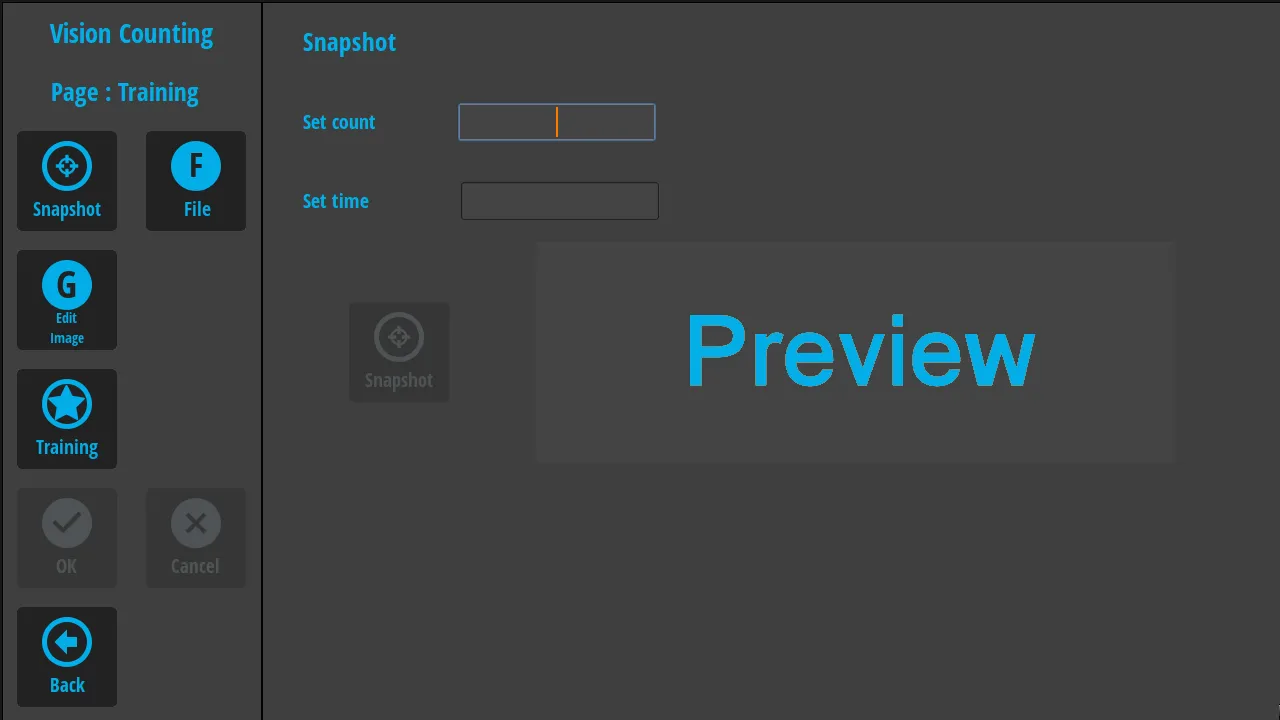
On the Training page, the user sets the number of images and the interval for the camera to take sample images (Snapshot), then trains the detection model from images of the parts and background images of the track with no parts on it. The manual recommends at least 200 part images per part model. The result is then saved as a new part model with a sample picture on the Add Product page.
- 2
Set the image area and counting line to match the track
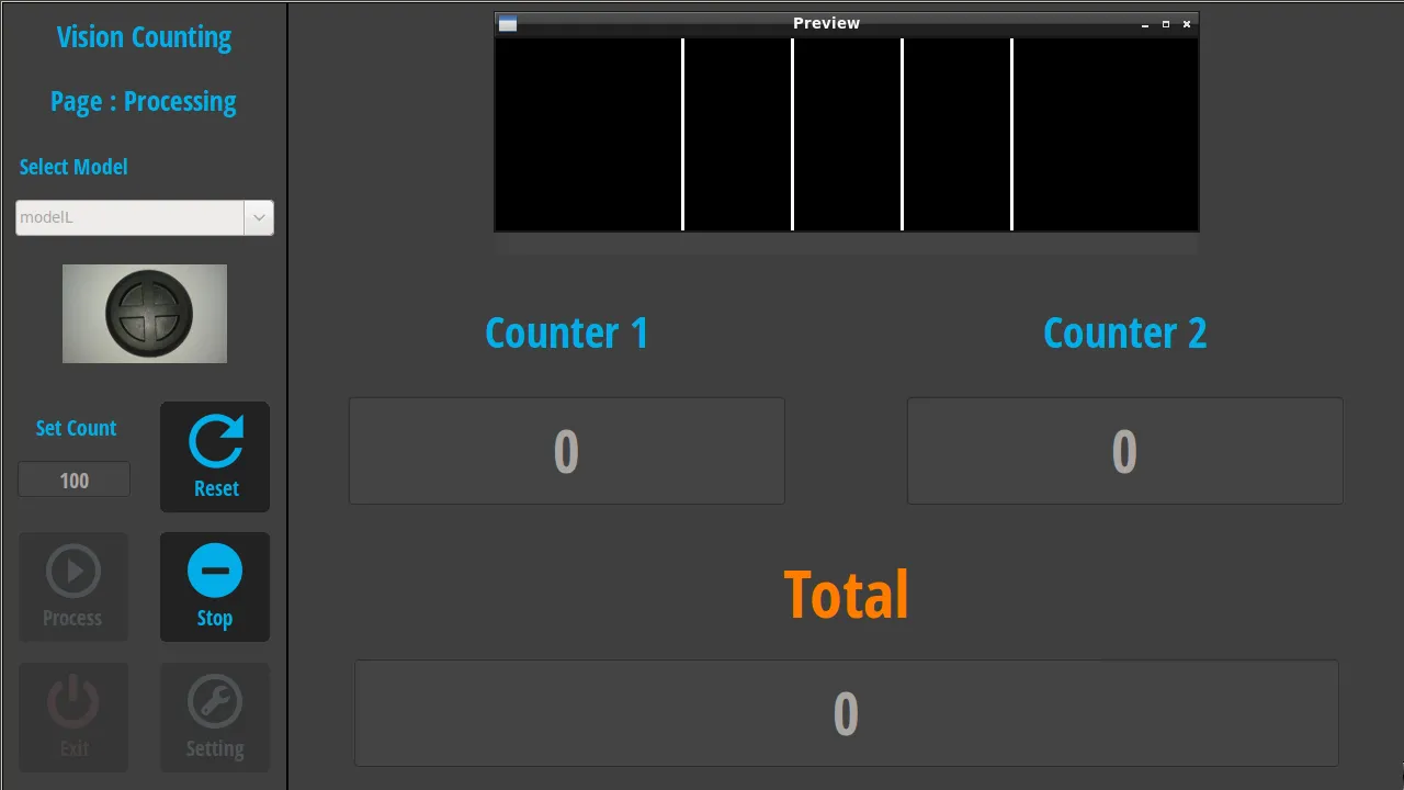
The person setting up the system defines the part of the image used for counting, divides the image into lanes matching the lanes of the vibrating track, and places the counting line (Line Counter) on the image.
- 3
Select the part model and set the count quantity
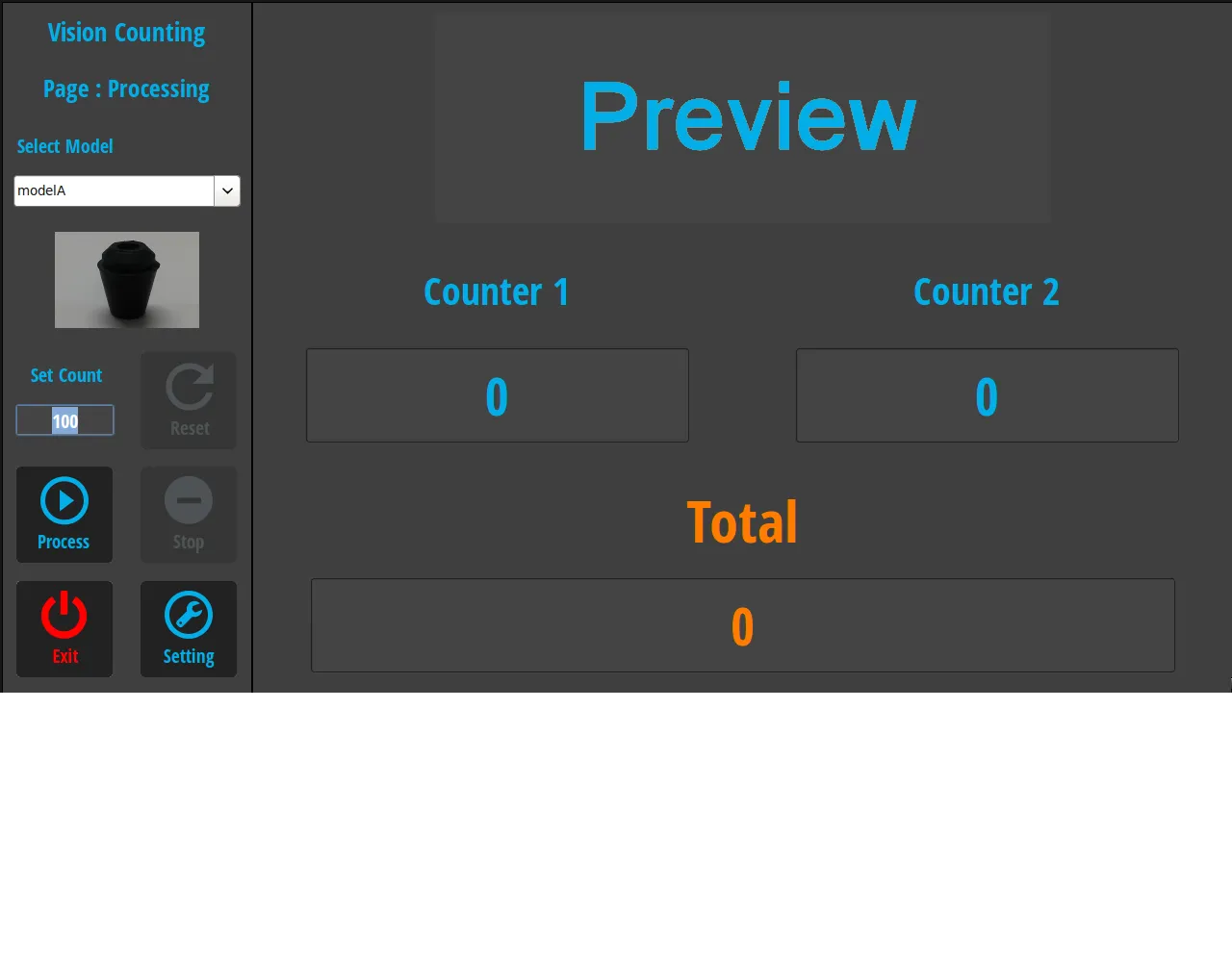
The user selects the part model from the list, enters the required quantity (Set Count) and presses Process. The screen shows 2 counter channels and the total, and has Stop and Reset buttons for use during counting.
- 4
Signal the machine to stop feeding
When the count is nearly complete, the system sends a signal on the first Output channel for the machine to stop the main track. When the count is complete, the system sends a signal on the second Output channel for the machine to stop the top-up track. The Tower Light turns green for about 4 seconds, and the program then starts a new counting cycle.
The Reset button on the machine is wired as 1 Input channel, so users can reset the counter from the machine. Users set the count quantity and press reset themselves. The system counts and signals according to the values the user has set.
Deliverables
We delivered the Vision Counting program together with the equipment set installed on the customer's machine and documentation for users. The deliverables were as follows.
- Vision Counting program: a part counting page, a page for adding, editing and deleting part models, and a Training page for taking sample images and training the model
- Hardware: Global Shutter camera, lens, 5 lighting sets, processing unit, display and router
- Installation: camera on a post above the vibrating track, camera position adjustment, and connection of the 24V power system to the machine's main power system
- Machine connection: 1 Input channel from the Reset button and 2 Output channels for stopping the feed track, along with the Tower Light
- Documentation: a user manual and an 8-item work checklist covering switching the machine, program and camera on and off, counting sample parts, and Input/Output signals
Work steps
This job ran from 2016 to 2017. It began with developing and testing the program, then test installation on the actual machine, followed by delivery of the equipment set and adjustment of the system to suit the machine. The work sequence was as follows.
- September–November 2016: developed the Vision Counting program, prepared the user manual and tested counting with the 5 part types
- December 2016: test installation of the system on the machine
- January 2017: delivered the equipment set, adjusted the lanes in the image to match the track, and defined how the Input/Output signals work with the machine
- May 2017: connected the 24V power system to the machine's main power system, prepared the 8-item work checklist and closed out the final phase
Confirmed results from the installation and job close-out
We installed and tested the Machine Vision Counter on the actual machine, delivered the equipment set in January 2017 and closed out the final phase in May 2017. Users at the machine can select the part model, set the count quantity and add new models themselves.
This page shows no accuracy figure because no numerical measurement was recorded. What was delivered is the equipment set, the user manual and the 8-item work checklist for checking the system.
What we learned
This job offers the following principles for camera-based part counting on machines.
- Parts must be in a lane before the camera can count them correctly. During on-site testing, parts that strayed out of their lane were not counted, so the machine's guide rails and the lane division in the image have to be designed together with the machine builder.
- Camera position and lighting must be finalised on the actual machine. On this job, several site visits were needed before the camera mounting position was finalised, so project plans should allow time for on-site adjustment and define the work checklist with the customer before testing begins.
- Separate the model's role from the counting rules. The model finds parts in the image, while the counting line, the set quantity and the Input/Output signals are rules that can be checked. Users therefore know why the machine stopped and can reset it from the machine.
How can you apply this approach to your machine?
If your machine feeds parts in lanes and must stop when the quantity is reached, you can use the same approach as this case: find the parts with a model, count with a counting line on an image divided into lanes, then send a signal to the machine. What has to be adapted is the lighting, the camera position and your machine's signals.
Reusable parts and parts that need adapting
| System part | Reusable | Needs adapting when |
|---|---|---|
| Finding parts in the image | Training a model per part model from part images and background images | Parts that differ from this case in colour, surface or size need new sample images and testing with actual parts |
| Counting | Dividing the image into lanes and counting with a counting line | If the track is not divided into lanes or parts overlap, check first whether counting with a counting line still works |
| Lighting and camera | Global Shutter camera with lighting above the track | If track speed, mounting height or ambient light around the machine differ, the camera position and lighting must be adjusted on the actual machine |
| Machine connection | Separate Output channels for nearly complete and complete counts, and an Input from the Reset button | If your machine uses signals or a power system different from this case, agree the connection points with the machine builder first |
- Prepare enough samples of every part model for taking images to train the model, as well as a track with no parts on it for background images
- Check whether the machine's guide rails can keep parts within their lanes
- Agree the Input/Output signals and the machine's power system with the machine builder from the outset
Read more
- Article: What is Vision Counting, and how are products counted with an AI camera?
- LearningCam: Edge AI camera for counting and inspecting parts by image
- Custom system development service
- On-site system and equipment installation service
- Case: spot counting system with Vision
- Case: line-side output counting with an app and barcodes
Technology used
Frequently Asked Questions
How does the system count multiple part models?
Each part type has its own detection model. Users capture sample images and train the model from the Training page, then save it as a new part type. Before counting starts, they simply select the part type from the list. In this case, testing covered 5 kinds of part: flat round parts in several sizes, parts with a centre hole, and stopper-type parts.
How does the system connect to the machine to stop the part feed?
The system sends 2 Output channels to the machine: the first when the count is nearly complete, to stop the main track, and the second when the count is complete, to stop the top-up track. The system receives 1 Input channel from the Reset button on the machine. The count is a value that users set themselves.
How many sample images of the parts need to be prepared?
In this case, the system's manual recommends at least 200 images of the part per part type, along with background images without parts. This figure is a recommendation for this system, not a requirement for every job. The Snapshot page helps set the camera to capture a specified number of images at a specified interval.
If a part moves out of its lane, can the system still count it?
No. During on-site testing in this case, parts that moved out of their lane were not counted. Before installation, the height of the guide rails and the lane arrangement therefore need to be reviewed together with the machine builder.
If we want a system like this, how much does it cost?
A camera counting system for machinery is designed to suit each site, so there is no standard price. You can request a quotation, and we will assess it based on part samples, the track characteristics and the signals that need to connect to the machine.