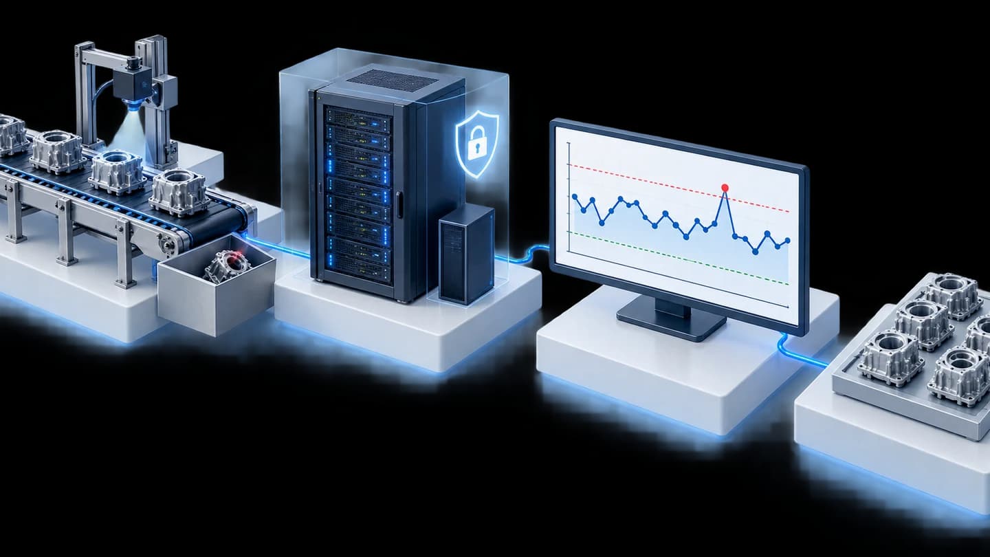





Image-based measuring microscope for automotive and electronic parts in Thailand
Organisation: Thai-German Institute (TGI)
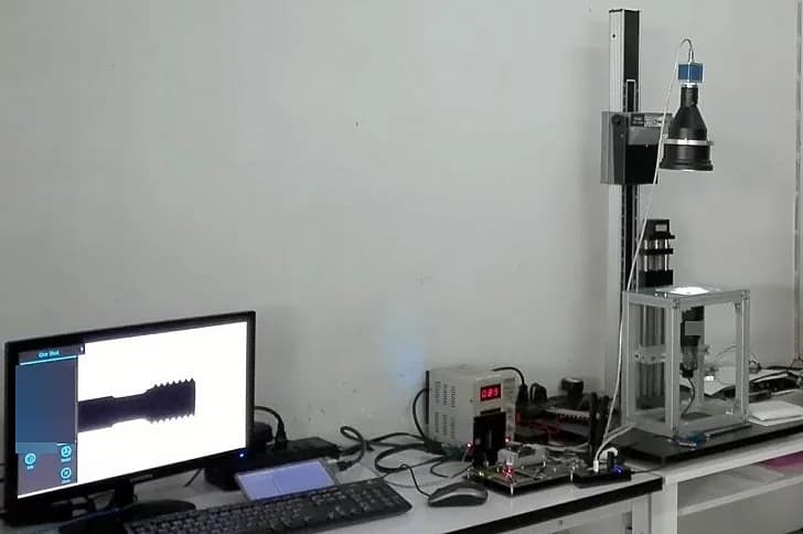
This measuring microscope was designed to measure multiple points on parts from photographs and automatically display pass/fail results against reference values, using a digital camera, telecentric lens, lighting and an embedded computer. We developed 1 prototype, starting in 2017, for the Thai-German Institute under the Ministry of Science and Technology’s technology-product development program for import substitution.
- Industry
- Automotive
- Year
- 2017
- Scope of work
- Project scope: design, build and test 1 workpiece measuring microscope · Input: images from a digital camera through a telecentric lens under a backlight + ring light set with adjustable brightness · Processing: an embedded computer locates the position and orientation of the workpiece, then measures distance, angle, circle, radius, area and perimeter from a single image · Set-up: users add or remove workpiece models, define measuring points from a CAD drawing or at the machine, and use CAD or a Master workpiece as the reference position · Output: pass/fail (OK/NG), measurement report, summary report, CPI report and user log · Design documents: 3 project reports, namely the work plan report, the progress report and the final report, which includes the mechanical drawings, electrical system drawings and source code
Summary
- We designed and developed 1 prototype workpiece measuring microscope, starting work in 2017, under the technology product development program for import substitution.
- The challenge was that vision-based workpiece measuring machines are mostly imported, expensive and so difficult to set up that users need image processing knowledge.
- The machine was designed to locate the workpiece in the image by itself, measure distance, angle, circle, radius, area and perimeter, then compare the results against the reference values for each workpiece model.
- The backlight makes the workpiece edges sharp and the telecentric lens keeps the workpiece size in the image from distorting with distance, so the software measures from a consistent image.
- The documents that confirm this work are the Inception Report, which sets out the designed functions, and the Final Report we prepared for the project. Accuracy values must be confirmed by testing with real workpieces before being used to judge workpieces.
The on-site brief
The vision-based workpiece measuring machines used by automotive and electronic parts factories are mostly imported, expensive and take many set-up steps, to the point that users need image processing knowledge. The project therefore needed a machine of this type developed in Thailand, with workpiece models that on-site users could set up themselves.
What we did
We were contracted to design and develop 1 prototype machine using a digital camera with a telecentric lens, a backlight and low-angle ring light set, and an embedded computer for image processing. The machine was designed to locate the workpiece in the image by itself, measure multiple points from a single image, then compare them against the reference values for the workpiece model to display a pass/fail result.
- Part with backlight + ring lightAdjustable brightness
- Camera with telecentric lensCapture part images
- Embedded systemDigital image processing
- Pass/fail reportCompare with reference values
Test results with real workpieces
The documents that confirm this work are the Inception Report, which sets out the designed functions, and the Final Report we prepared for the project. There are no publishable figures for the machine’s resolution and accuracy, so this page describes only the designed functions. Under the project conditions, the prototype machine is to pass to the Thai company taking part in the project as the user.
How the brief came about
This workpiece measuring microscope was designed to measure multiple points on small workpieces from images and to let on-site users set up workpiece models themselves. The challenge came from automotive and electronic parts factories that must measure multiple points on small workpieces before shipping to customers. Most vision-based measuring machines on the market are imported, expensive and take many set-up steps, to the point that users need image processing knowledge.
In 2017, we were contracted to design and develop 1 prototype workpiece measuring microscope for the Thai-German Institute, under the Ministry of Science and Technology’s technology product development program for import substitution. The program aimed to reduce machinery imports and to transfer vision inspection machine design technology to Thai companies, with a Thai company taking part in the project as the machine user.
What is a workpiece measuring microscope?
A workpiece measuring microscope is a vision-based workpiece measuring machine. It uses a camera and lens to capture an image of the workpiece, and software then measures dimensions at multiple points from that image.
Requirements and constraints
The prototype machine had to measure multiple points on a workpiece from images, and users without image processing knowledge had to be able to set it up themselves. The main requirements and constraints under the project scope are as follows.
- Develop 1 prototype machine complete with camera, lens, lighting set, computer and image processing software.
- Measure multiple positions from the same image, then compare them against the reference values for the workpiece model.
- Users can add or remove workpiece models themselves and define measuring points from a CAD drawing or directly at the machine.
- Workpieces placed at an angle must still be measurable, using a CAD drawing or a prototype workpiece (Master) as the reference position.
- Under the project conditions, the commissioning institute obtains the rights to the knowledge, documents and designs of the machine, and the Final Report must include the mechanical drawings, electrical system drawings and source code.
How was the prototype machine designed to measure workpiece dimensions from images?
The prototype machine was designed to measure dimensions from photographs of the workpiece. The backlight helps make the workpiece edges sharp, and the telecentric lens helps keep the workpiece size in the image from distorting with distance. The embedded computer was then designed to locate the workpiece, measure multiple points and compare them against the reference values for that model.
We chose this approach because the challenge called for both trustworthy measurements and simple set-up. The lighting and lens keep the image of the workpiece edges consistent before it reaches the software, while defining measuring points from a CAD drawing or at the machine was designed to let users set up new workpiece models without writing image processing steps themselves. The steps below show how the prototype machine was designed to work.
- 1
Set up the workpiece model
The user adds a workpiece model and defines the measuring points from a CAD drawing or directly at the machine, along with the reference value for each point.
- 2
Illuminate and capture
A backlight and low-angle ring light set with adjustable brightness makes the workpiece edges sharp. A digital camera captures the image through a telecentric lens.
- 3
Locate and measure the workpiece
The embedded computer processes the image to find the position and orientation of the workpiece, then measures distance (width, height), angle, circle, radius, area and perimeter.
- 4
Display results and issue reports
The system compares the measured values against the reference values, displays a pass or fail result (OK/NG) and issues a Measurement Report, a Summary Report, a CPI report and a User Log Report.
System components
The work scope under the project is 1 prototype machine and 3 reports. The list below shows the components specified by the project scope and the machine’s design.
- Prototype machine: digital camera, telecentric lens, backlight + ring light set with adjustable brightness, and embedded computer
- Measuring software: locate the workpiece in the image, take several types of dimensional measurement, manage workpiece models and use a CAD drawing or Master as the reference position
- Machine reports: pass/fail result, measurement report, summary report, CPI report and user log
- Project reports: work plan report, progress report and final report including the mechanical drawings, electrical system drawings and source code
Documents and confirmed results
What can be confirmed are the functions designed in the Inception Report and the Final Report we prepared for the project. There are no publishable figures for the machine’s resolution and accuracy, so we do not state these values in this case.
Under the project conditions, the prototype machine is to pass to the Thai company taking part in the project as the user, while the knowledge, documents and designs of the machine belong to the commissioning institute.
What we learned
This work offers the following principles for vision-based workpiece measurement.
- Measuring with images starts with lighting and lenses, before software. The prototype machine was therefore designed to use a backlight to make the workpiece edges sharp and a telecentric lens to keep the size in the image from distorting with distance. The goal is for the software to measure from a consistent image.
- A measuring machine for on-site use must allow workpiece models to be set up without image processing knowledge. Defining measuring points from a CAD drawing, and using CAD or a Master workpiece as the reference position, were designed to let the quality team do the set-up themselves.
- Design targets are not yet actual measurement results. A measuring machine’s resolution and accuracy values must come from testing with real workpieces, with documents confirming the results, before being used to judge workpieces.
How can you apply this approach to your workpiece measurement?
If you need to measure multiple points on small workpieces before shipping to customers, you can use the framework of this prototype machine as a design starting point: a camera with a telecentric lens, a lighting set, software that sets measuring points from a CAD drawing, and pass/fail reports. What needs adapting is the camera, lens and lighting set, to match the size, surface and tolerance of your workpieces.
Reusable parts and parts that need adapting
| System part | Reusable | Needs adapting when |
|---|---|---|
| Lighting set | Backlight for workpiece edges, and low-angle ring light with adjustable brightness | If the surface or colour of the workpiece differs from the original work, the lighting arrangement must be tested with real workpieces |
| Camera and lens | The principle of using a telecentric lens to keep the size in the image from distorting with distance | If the workpiece size or required resolution differs, a new camera and lens model must be selected |
| Model and measuring point set-up | Define measuring points from a CAD drawing or at the machine, and use CAD or a Master as the reference position | If there is no CAD drawing, measuring points must be defined at the machine from real workpieces |
| Reports | Pass/fail result, measurement report, summary report and usage log | If your quality team or customer specifies its own report format, or results must be sent to other factory systems |
| Use on the production line | The prototype machine’s design serves as a starting point for design | If it must be used to judge real workpieces, it must be tested with real workpieces and its accuracy confirmed before the final specification is set |
Read more
- InGauge — automatically sends values from digital measuring instruments to a computer
- InQC — SPC app on Android for recording and tracking measurement values
- Case: scratch inspection and workpiece measurement with Vision
- Case: Machine Vision laboratory with Deep Learning (MVDeep)
- Case: can seam inspection machine (DSIS) developed to replace imported machines
- Custom system development service
- Article: How AI Vision quality inspection works
Technology used
Frequently Asked Questions
What can this vision-based workpiece measuring machine measure?
The prototype machine was designed to measure a workpiece’s distance (width, height), angle, circle, radius, area and perimeter from images, then compare them against the reference values for each workpiece model to display a pass or fail result.
Why does a vision-based measuring machine need a telecentric lens and a backlight?
A backlight makes the workpiece edges sharp, while a telecentric lens keeps the workpiece size in the image from distorting with distance, so the software measures from a consistent image. If the surface or colour of your workpiece differs, the lighting arrangement must first be tested with real workpieces.
Is this case the MVDeep project?
No. MVDeep (Machine Vision laboratory with Deep Learning) is a separate project with the same client. See the Machine Vision laboratory with Deep Learning case for details.
Can this machine model be purchased? How much does it cost?
The machine in this case is the project's prototype, not a finished product. If you need an image-based system for measuring workpiece dimensions, we will first look at your workpieces and measuring points, then prepare a quotation according to the scope of work.
What should I prepare before discussing an image-based measuring machine?
Please prepare samples of workpieces that pass and fail, a CAD drawing of the workpiece (if available), a list of the points to be measured with their tolerances, and the report format you need.