




System that reads balancing machine values with OCR, calculates vibration values and decides OK/NG for an automotive parts manufacturer in Thailand
Customer: Automotive parts manufacturer (Japanese conglomerate)
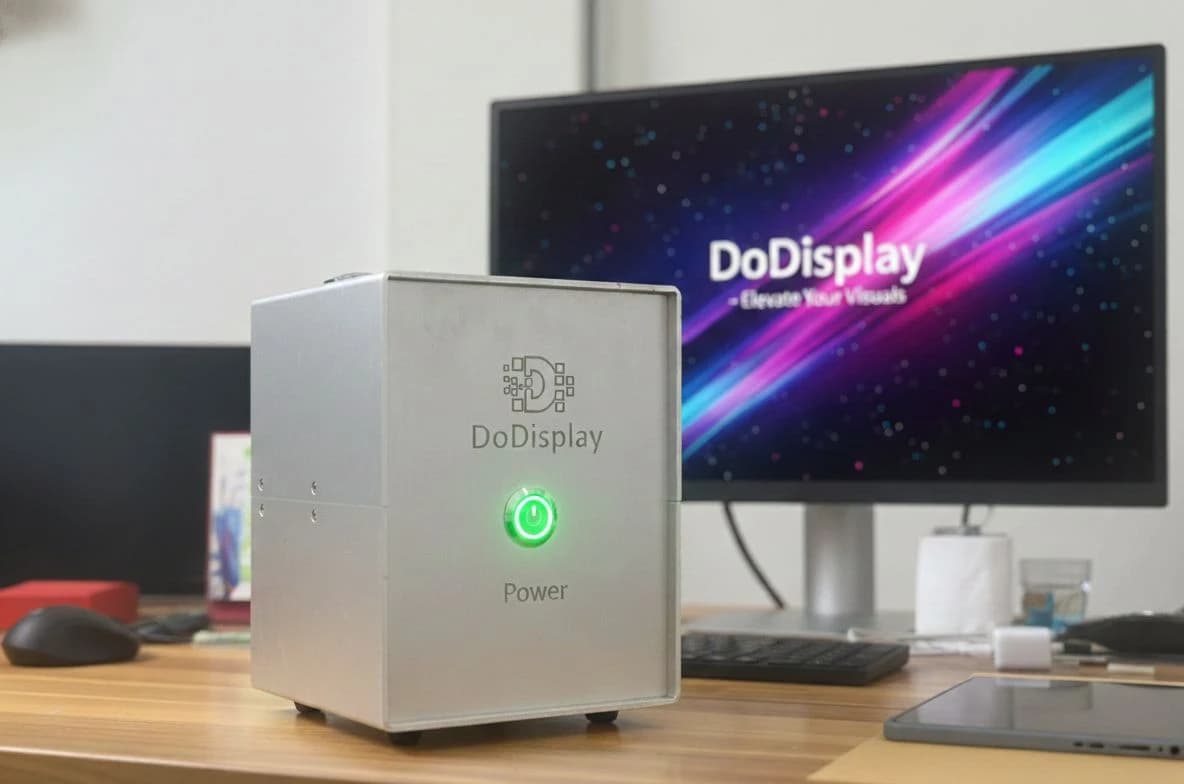
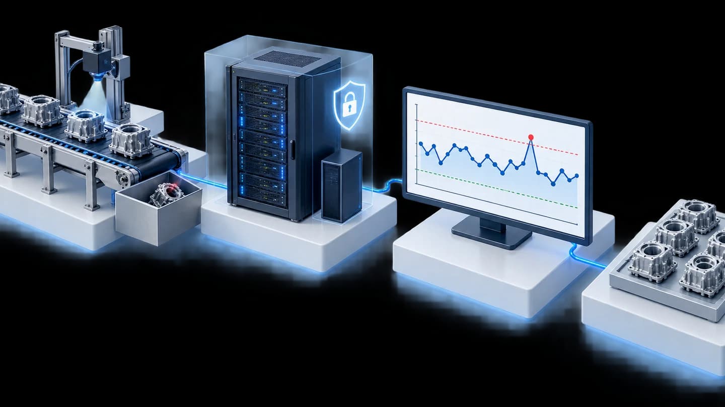
Auto Calculate Vibration is a system that reads unbalance values from a fan balancing machine's screen with OCR, calculates vibration values and decides OK/NG (pass/fail) according to the criteria for each model, instead of typing figures into Excel. We installed this system with DoDisplay, a 10-inch tablet and a Wi-Fi 6 Router on 1 fan assembly line at an automotive parts manufacturer in Thailand in 2025–2026.
- Fan balancing machine screenVideo signal split by a Splitter
- DoDisplay reads figures with OCRUpper / Lower / Static / Couple
- Auto Calculate VibrationCalculates vibration value, decides OK/NG
- Dashboard on tabletVia Wi-Fi Router
- Tower Light and NASResult light + history stored with images
- Industry
- Automotive
- Year
- 2025–2026
- Scope of work
- Supply and installation of DoDisplay, a 10-inch tablet, a tablet stand and a Wi-Fi 6 Router; development of the Auto Calculate Vibration software (Dashboard, Model Configuration, History and file export) for 1 fan assembly line; then improvements adding a Tower Light via IoT Gateway and I/O Module, NAS, a summary Excel file and a password for the settings page.
- Duration
- Ordered in December 2025, first set delivered in March 2026 and improvements delivered in September 2026
Summary
- Auto Calculate Vibration reads unbalance values from a fan balancing machine's screen with OCR, calculates vibration values and decides OK/NG according to the criteria for each Part Number, instead of typing figures into Excel.
- DoDisplay receives the screen image through a Splitter and reads 4 values (Upper, Lower, Static, Couple) without modifying the machine's existing program, and the machine can keep working even if DoDisplay fails.
- Every result is stored with the screen image that was read, and the formula settings page requires a password before access.
- We delivered the first set in March 2026 and the improvements (Tower Light, NAS, summary Excel file, password) in September 2026.
- Project close-out and confirmation of the processing test results are in progress, and in 2026 the customer ordered the same system to be installed at another factory as well.
The on-site brief
Operators read Static and Couple unbalance values from the balancing machine's screen, then typed them into an Excel formula on a tablet to convert them into vibration values. The customer wanted a system that reads the values, calculates and decides the result with an alert signal, instead of manual typing and rechecking.
What we did
We connected DoDisplay (a VGA screen video input box) to the balancing machine's screen through a Splitter (video signal splitter), then used OCR (Optical Character Recognition, reading characters from images) to read 4 unbalance values: Upper, Lower, Static and Couple. The Auto Calculate Vibration software we developed feeds the Static and Couple values into a formula, decides OK/NG according to the criteria for each Part Number (the workpiece model code) and shows the result on a tablet. A later round of improvements added a Tower Light, NAS for storing history, a summary Excel file and a password for the settings page.
Current status
We delivered the first set of the system in March 2026 and delivered the improvements in September 2026. Operators no longer have to type figures into Excel, and every result has a stored screen image that can be checked later. Project close-out and confirmation of the processing test results are in progress.
How the brief came about
The problem in this case was to stop typing unbalance values into Excel by hand and to have the system decide the fan's vibration result from values read directly from the machine. On the fan assembly line, the balancing machine already showed unbalance values on its computer screen, but those values were not yet the vibration value used to decide the result.
Previously, operators read the Static and Couple values from the screen, then typed them into an Excel formula on a tablet to convert them into vibration values. The team leader had to recheck them. If a figure was mistyped, the decision would also be wrong, and fans and motors vibrating beyond the standard could pass through.
What are Static and Couple values?
A rotating part vibrates when its weight is unevenly distributed around the axis. Static is the unbalance that makes the whole part swing out to one side, while Couple is the unbalance on two sides that makes the rotating axis rock. The balancing machine measures these two values, and the factory's formula converts them into a vibration value to decide whether the fan passes.
Requirements and constraints
The new system had to read values from the existing balancing machine without disturbing its operation. The main requirements and constraints were as follows.
- Do not modify the balancing machine's existing program, because it cannot be changed to calculate or output values itself as this requirement needs.
- The machine's original screen must display as normal, and the machine must keep working even if the new equipment fails.
- Read the unbalance angle and magnitude for all 4 fields: Upper, Lower, Static and Couple.
- Formula coefficients and OK/NG criteria can be set separately for each Part Number. These values are the customer's data, so we do not publish them.
- Operators view results on a Wi-Fi-connected tablet, and every result must have evidence that can be checked later.
Why we read values from the screen image instead of modifying the machine's program
We read values from the screen image because the figures needed are already shown on the machine's screen, and this method does not touch the balancing machine's existing program. The Splitter (video signal splitter) sends the same image to both the original screen and DoDisplay, so operators still see the machine's screen as normal. If DoDisplay fails, the machine and its existing program can keep working.
DoDisplay is a VGA screen video input box that uses OCR (Optical Character Recognition, reading characters from images) to read figures on the screen. The working steps are as follows.
- 1
Split the video signal from the machine's screen
The video signal splitter sends the signal from the balancing machine's computer to the original screen and DoDisplay at the same time.
- 2
Read figures once the on-screen values settle
When the Measuring message disappears from the screen, the system waits for the on-screen values to settle and then reads them. DoDisplay reads the unbalance angle and magnitude for the Upper, Lower, Static and Couple fields.
- 3
Calculate and decide the result
The Auto Calculate Vibration software feeds the Static and Couple values into the formula to calculate the vibration value, then compares it with the criteria for that Part Number. The result is OK or NG.
- 4
Show results on the tablet and signal light
Operators see the figures for every field with the OK/NG result on the tablet's Dashboard (results summary screen), and the Tower Light (signal light at the front of the machine) shows the result on the line.
- 5
Store history with screen images
Every result is recorded with the screen image that was read, can be searched by model and date range on the History page, and can be exported as an Excel file.
Deliverables
We delivered the first set of the system in March 2026 and the improvements in September 2026, for 1 fan assembly line. The items delivered in each round were as follows.
Equipment and software delivered in each round
| Round | Hardware | Software |
|---|---|---|
| First set (March 2026) | DoDisplay, 10-inch tablet, tablet stand mounted on the rack cabinet and Wi-Fi 6 Router | Auto Calculate Vibration with Dashboard, Model Configuration (setting formulas and criteria by Part Number) and History pages, plus file export |
| Improvements (September 2026) | Tower Light controlled via IoT Gateway and I/O Module (a device that receives commands to switch the light on and off) and NAS (a network data storage device) for storing history | Summary Excel file and a password before entering the settings page |
How this work was carried out and extended
This work began with 1 fan assembly line, then added capabilities in the improvement round. The sequence of work on the first line, according to the project documents, was as follows.
- December 2025: The customer ordered equipment and software for the fan assembly line
- March 2026: We delivered the first set of the system
- September 2026: We delivered the improvements, namely the Tower Light, NAS, summary Excel file and settings page password
In 2026, during the work on the first line, the customer ordered the same system to be installed as well on the motor line of another factory. This page does not yet include the results of that work.
Confirmed results and work in progress
The results that can be confirmed at present are delivery according to the documents and the end of typing figures into Excel on the fan assembly line. We delivered the first set of DoDisplay, a 10-inch tablet and a Wi-Fi 6 Router in March 2026, and delivered the improvements, namely the Tower Light, NAS, summary Excel file and settings page password, in September 2026.
The system reads the values, calculates and shows the OK/NG result for operators on the tablet. Every result has a stored screen image for later checking, and the installation is designed so that the balancing machine can keep working even if DoDisplay fails.
Project close-out and confirmation of the processing test results with the customer are in progress, so we have not yet published figures for time per piece or OCR accuracy.
What we learned
This work offers the following principles for reading values from measuring instruments that cannot output data.
- When the existing machine's program cannot be modified, read from what the machine already displays and connect the new equipment in parallel with the existing setup. If the new equipment fails, the machine must still be able to keep working.
- Reading values from a screen must happen at the moment the value is final. In this work, the system waits for the Measuring message to disappear and the on-screen values to settle before reading.
- An automatic decision can be trusted when every result can be checked later. This work therefore stores a screen image with every result and restricts changes to formulas and criteria with a password.
How to apply this approach to measuring instruments in your factory
If your measuring or test instrument shows figures on its screen but cannot output data, you can use the same approach as this case: capture the screen image, read the figures with OCR, calculate using your factory's formula, then show the result and store the image as evidence. The parts to adapt are the image capture and the calculation formula.
Reusable parts and parts that need adapting
| System part | Reusable | Needs adapting when |
|---|---|---|
| Screen image capture | Splitter and DoDisplay for VGA screens | If the machine's screen uses a different type of video signal, the signal type must be checked first. |
| Reading figures | OCR reads the on-screen values once they have settled | If the screen layout or the position of figures differs from this case, reading must be configured and tested again. |
| Calculation and decision | Model Configuration page, which sets formulas and criteria by Part Number | If your formula uses values other than Static and Couple, the formula in the software must be adjusted. |
| Result notification | Dashboard on the tablet and Tower Light | If you want the result to go on to command machinery or other systems, further design and testing are needed. |
| History storage | History page with screen images, Excel export and NAS | If history must be kept for longer or across several lines, the storage capacity must be recalculated. |
- Prepare clear calculation formulas, coefficients and pass/fail criteria for each model, because the system decides according to the values set.
- Check the machine screen's video signal type (such as VGA) and the position of figures on the screen, in order to design the OCR reading.
- Test with similar-looking digits under the line's actual lighting and screen brightness before going live.
- Set an acceptable time per piece that keeps up with the production cycle, and decide who is authorised to change the formula settings.
Start with real screenshots
Several screenshots of the machine during actual measurement, covering both passed and failed pieces, are the first data we use to assess how accurately OCR can read the values.
Read more
- System development service tailored to factory requirements
- On-site system and equipment installation service
- System care and maintenance service
- Case: Sending digital vernier caliper values to automatic QC reports
- Case: OCR camera reading component reel labels and printing barcode stickers
- Case: saving microscope images to a designated folder
- Case: P-Chart web app on a server in the factory
- Article on SPC and P-Chart for factory managers
Technology used
Frequently Asked Questions
Does the program need changing, or the existing balancing machine replacing?
Not in this case. DoDisplay receives the image from the machine's screen through a Splitter and reads the figures with OCR. The machine's program continues to work as before, and the installation is designed so that the machine can keep running even if DoDisplay develops a fault.
If OCR misreads a figure, how can this be detected?
Every result is stored together with the screenshot it was read from, and users can open it to compare on the History page. Reducing the chance of misreads has to be done from the installation stage, for example by testing with similar-looking digits and the line's actual screen conditions.
Can we change the formula or judgement criteria ourselves?
Yes. The Model Configuration page is used to set the formula coefficients and criteria separately for each Part Number, and following the improvement work, users must enter a password before accessing this page.
How quickly can the system give a result?
Confirmation of the processing test results with the customer is in progress on this project, so we have not yet published a time-per-piece figure. For your line, the time per piece must be tested against your actual production cycle before use.
If I want a system like this on another machine, how much does it cost?
There is no standard price, but you can request a quotation. We assess it based on the type of video signal from the screen, the number of values to be read, the calculation formulas, and the result notification or storage devices required.
Products used in this case