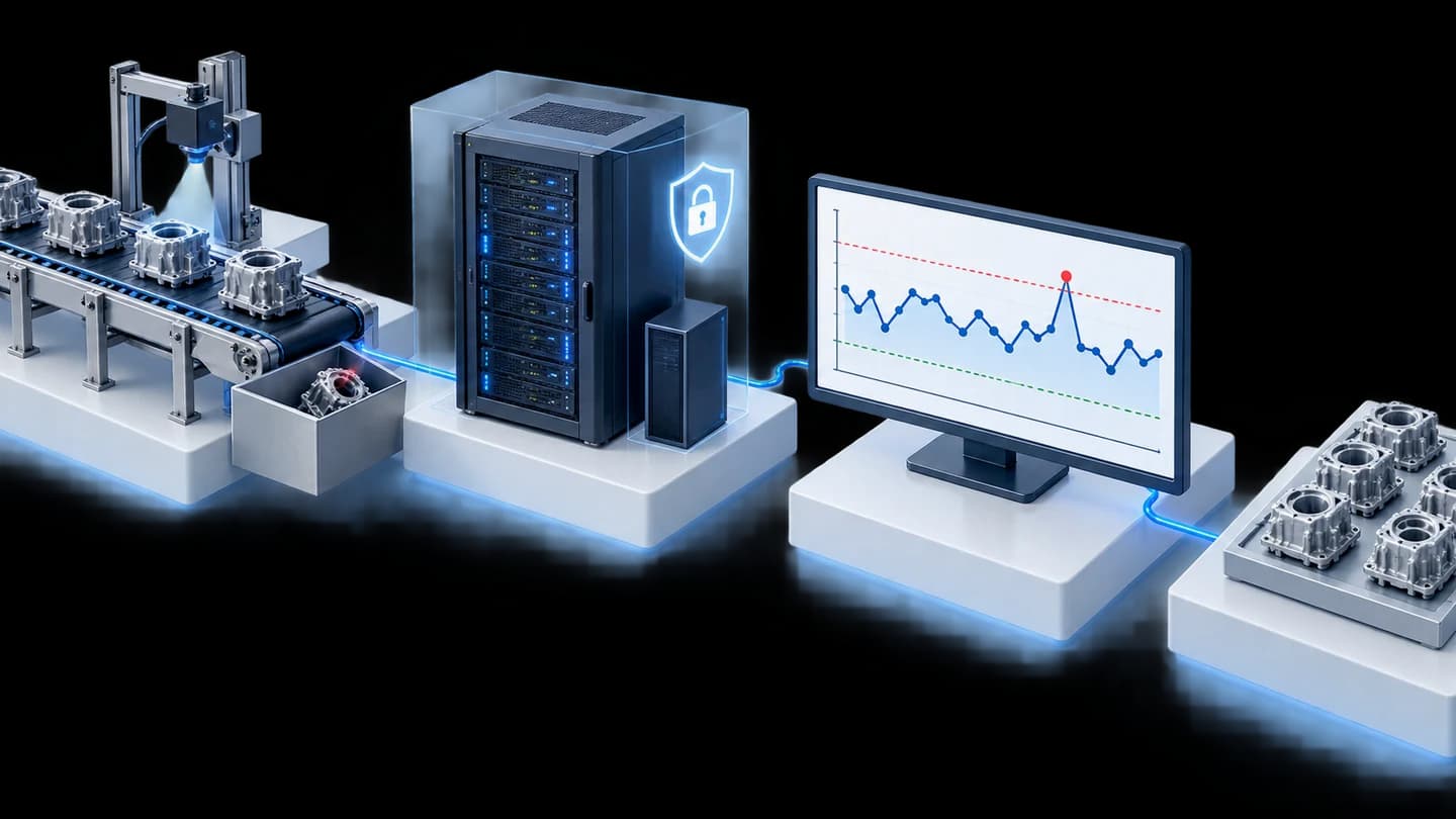





Camera system for airbag component assembly inspection, for the automotive parts industry
This Machine Vision system checks that the plastic components of airbag assemblies in 4 models have all their plastic pins fitted, and that the slide plate, black tape and adhesive pad are correctly positioned, then sorts good parts from defective parts. We built a prototype (PoC) on a test rig in 2016–2017 with a Cube camera and a Medusa processing unit, and carried out per-station testing with good and defective workpieces, 100 times each.
- Industry
- Automotive
- Year
- 2016–2017
- Scope of work
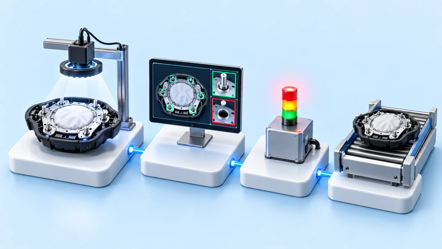
- Assembly inspection camera system on a test rig — Image input: Cube camera above the workpiece at a distance of 20 cm, 8 mm lens and Area Light · Processing: Medusa processing unit that can connect 2 cameras, with an image processing program covering 5 inspection items (plastic pins, slide plates, black tape, adhesive pads, and sorting good/defective parts) on workpieces in 4 models, both left-hand and right-hand parts · Workstation signals: receives signals from 2 switches simultaneously and outputs 24 V on 3 channels (pass, fail, status) · Additional program for PA66-GF30 and PP-GF30 black plastic parts that distinguishes round nuts from square nuts · Per-station testing with good workpieces 100 times and defective workpieces 100 times
Summary
- A camera system for inspecting the assembly of plastic airbag components in 4 models, both left-hand (LH) and right-hand (RH) parts. We built it as a prototype (PoC) on a test rig in 2016–2017.
- The test rig uses a Cube camera above the workpiece, an 8 mm lens, an Area Light and a Medusa processing unit. The image processing program inspects plastic pins, slide plates, black tape and adhesive pads, and sorts good parts from defective parts, 5 items in total.
- The test report concludes that all 5 items could be inspected, and in per-station testing the system judged good workpieces 100 times and defective workpieces 100 times, correctly every time.
- The per-station prototype receives signals from 2 switches simultaneously and outputs 24 V on 3 channels, separated into pass, fail and status, to the equipment at the workstation.
The on-site brief
The plastic components of the airbag assembly come in 4 models, each with a left-hand part (LH) and a right-hand part (RH), and plastic pins, slide plates, tape or adhesive pads must be fitted completely and in the correct position. The customer wanted a camera system that could carry out this assembly inspection on its own, sort good parts from defective parts, and send inspection results as 24 V signals to the equipment at the workstation.
What we did
We set up a test rig with a Cube camera, an 8 mm lens, an Area Light and a Medusa processing unit, then wrote an image processing program covering 5 inspection items. We then tested the program per workstation against the input and output signal requirements, and added an inspection program for black plastic parts that distinguishes round nuts from square nuts.
Test results with real workpieces
The test report concludes that the prototype could inspect all 5 items, and that pin inspection on Model B and adhesive pad position inspection on Model D use 1 camera. In per-station testing on the test rig, the system judged good workpieces 100 times and defective workpieces 100 times, correctly every time. These results were measured on the test rig. Use on a production line requires further trials under on-site lighting conditions and work timing.
How the brief came about
The brief for this work was to have a camera confirm that the plastic components of the airbag assembly were complete and correctly positioned before going on to the next step. The parts tested covered 4 models, which the documents call Model A to Model D, and each model has a left-hand part and a right-hand part. Plastic pins must be fitted on the workpiece, and some models must also have a slide plate, black tape or an adhesive pad.
The airbag is a safety component. A missing pin or a slightly misaligned adhesive pad is hard to see by eye, especially when there are several models and the left-hand and right-hand parts look similar. The customer therefore wanted a Machine Vision system (a system that uses cameras and software to inspect workpieces in place of the human eye) that inspects every part against the same criteria.
Requirements and constraints
We set out the prototype's requirements in the job's requirements document and the per-workstation requirements. The system must inspect 5 items on workpieces in 4 models, and must send inspection results as electrical signals to the equipment at the workstation.
- Check that plastic pins are fitted at every point, on the workpiece plates of all models
- Check the position of the slide plate on Model A, the black tape on Model C and the adhesive pad on Model D
- Sort good parts from defective parts automatically
- Support both left-hand (LH) and right-hand (RH) parts of every model
- The per-station prototype must receive signals from 2 switches simultaneously and output 24 V on 3 channels: pass, fail and status
- On the black plastic parts (PA66-GF30 and PP-GF30 are grades of glass-fibre-reinforced plastic), round nuts must be distinguished from square nuts, to catch cases where they are fitted in each other's positions
Why an overhead camera, an Area Light and image processing
We placed the camera above the workpiece and used an Area Light because this work needs the edges of the pins, tape and adhesive pads to be clear enough for the program to separate them from the workpiece background. The test rig uses a Cube camera at a distance of 20 cm with an 8 mm lens. Images from the camera go to a Medusa processing unit, which can connect 2 cameras, and an image processing program then locates the points to inspect on each model.
We started with a test rig because we first had to confirm that the camera images showed every inspection point on all models, and how many cameras were needed. The test rig results could therefore tell us which inspection points can share a single camera.
What is an Area Light?
An Area Light is a light panel that gives even illumination over a wide area. It is used to reduce shadows and reflections on the workpiece, so that the edges of pins, tape or adhesive pads are clear enough for the program to separate them from the workpiece background.
What we built and tested
This prototype has 2 parts: the hardware test rig, and the inspection program that we wrote and tested on that rig.
- Hardware test rig: Cube camera, 8 mm lens, Area Light and Medusa processing unit
- Assembly inspection program covering 5 items for workpieces in 4 models
- Per-workstation prototype program that receives signals from switches and sends inspection results to the workstation as electrical signals
- Inspection program for black plastic parts that distinguishes round nuts from square nuts
Test sequence
We tested in 3 stages: first confirming that every item could be inspected, then testing per station against the signal requirements, and adding a program for the black plastic parts.
- Test inspection of the 5 items on the test rig and summarise the results in a test report
- Test the per-workstation prototype program with good and defective workpieces
- Add an inspection program for PA66-GF30 and PP-GF30 black plastic parts that distinguishes round nuts from square nuts
Details of test results on real workpieces
The test report concludes that the prototype could inspect the assembly of plastic airbag components in 4 models on all 5 items. Pin inspection on Model B and adhesive pad position inspection on Model D use 1 camera.
In per-station prototype testing on the test rig, the system judged good workpieces 100 times and defective workpieces 100 times, correctly every time. These results were measured on the test rig, where camera distance and lighting can be held constant. Use on a production line requires further trials under on-site lighting conditions and work timing.
What we learned
This work offers 3 principles for camera-based assembly inspection.
- Test both good and defective parts, and report the results separately. Correct results on good parts alone do not show that the system can catch defective parts, so this work tested good and defective workpieces 100 times each.
- The test sample set must cover everything that makes images differ, such as workpiece model, left-hand versus right-hand part, and pin colour. In this work, white and blue pins had to be tested separately.
- Define the input and output signals with the workstation from the prototype stage. Inspection results from the camera become usable when the equipment at the workstation can receive the pass, fail and status signals as agreed.
How to apply this approach to your assembly line
If your assembly line must confirm that pins, clips, tape or adhesive pads are all present and correctly positioned, you can use the same approach as this prototype: an overhead camera, lighting that gives even illumination, a point-by-point inspection program, and pass / fail signals to the workstation. What must be adjusted is the camera distance, lens, lighting and number of cameras, according to the size and colour of your workpieces.
Reusable parts and parts that need adapting
| System part | Reusable | Needs adapting when |
|---|---|---|
| Camera and lighting | Camera above the workpiece with an Area Light | If the workpiece is larger, has obscured points or has a surface that reflects light differently from this case, the camera distance, lens and lighting must be tested again. |
| Inspection program | Checking that all sub-parts are present, and checking the position of tape or adhesive pads | If a sub-part's colour is close to the workpiece background colour, or new models are added, testing is needed with sample workpieces of each model. |
| Number of cameras | Inspecting several points with 1 camera when the inspection points are in the same image | If the inspection points are on different sides of the workpiece, the number of cameras must be assessed again. |
| Workstation signals | Pass, fail and status signals on separate channels | If the equipment at the workstation accepts a different type of signal, the number of channels and the voltage must be agreed again. |
| Confirming results | Testing good and defective parts separately on a test rig | Before actual use, trials on the production line are required, because on-site lighting and work timing differ from the test rig. |
- Prepare sample workpieces, both good and defective, for every model, both left-hand and right-hand parts
- Specify clearly which points must be inspected, and whether each point only needs a present-or-absent check or a position check as well
- Agree the input and output signal format with the equipment at the workstation from the start
- Plan a trial on the production line before full-scale use
Read more
- AI / IoT consulting and system design service that starts with a prototype (PoC)
- Custom inspection and control system development service
- Task Cam: off-the-shelf camera for assembly sequence inspection
- Prototype case: sorting recycled paper by colour shade with a Cube camera and a Medusa processing unit
- Case: Machine Vision demo kit for automotive parts
- Article on choosing an AI inspection camera: off-the-shelf Task Cam or custom-built Machine Vision
- Article: How AI Vision Inspection differs from the human eye
Technology used
Frequently Asked Questions
What can this prototype inspect?
This prototype inspects 5 items: plastic pins on the workpiece plates of all models, the slide plate on Model A, the black tape on Model C, the adhesive pad on Model D, and automatic sorting of good parts from defective parts. The test report concludes that all 5 items could be done.
How many cameras are needed?
In this work, pin inspection on Model B and adhesive pad position inspection on Model D use 1 camera. For your work, the number of cameras depends on the size of the workpiece and the location of the inspection points. We assess this from sample workpieces before confirming.
How reliable are the test results?
In per-station prototype testing, the system judged good workpieces 100 times and defective workpieces 100 times, correctly every time. These results were measured on the test rig. Before use on your production line, further trials under on-site lighting conditions and work timing are required.
How does the system send inspection results to the equipment at the workstation?
The per-station prototype requirements specify receiving signals from 2 switches simultaneously and outputting 24 V on 3 channels, separated into pass, fail and status. The equipment at the workstation then uses these signals as the factory specifies.
What needs to be prepared before testing with your workpieces?
Prepare sample parts, both good and defective, for every model and for both left-hand and right-hand parts. Identify the points to be inspected and the signal format that the equipment at the workstation can receive. The sample set must cover everything that makes the images differ. In this work, white pins and blue pins must be tested separately.